
Device and method for detecting and positioning leakage of gas transmission pipeline based on conventional data and sound wave signals

A leak detection and gas pipeline technology, applied in pipeline systems, gas/liquid distribution and storage, mechanical equipment, etc., can solve the problems of inaccurate positioning, ignoring the low-frequency part of audible sound, and not proposing the installation distance of sonic sensors, etc. Accurate positioning

Inactive Publication Date: 2012-07-11
CHINA UNIV OF PETROLEUM (EAST CHINA)
View PDF7 Cites 57 Cited by
  • Summary
  • Abstract
  • Description
  • Claims
  • Application Information

AI Technical Summary

Problems solved by technology

[0008] (1) Both the infrasound and the low-frequency part of the audible sound of the leak signal can be used as the characteristic frequency band of leak detection, and both can be transmitted remotely. However, the above patents only study the infrasound part of the signal, ignoring the low-frequency part of the audible sound , which is not conducive to signal feature extraction and can easily cause false positives
[0009] (2) None of the above patents clearly proposes how to accurately eliminate external interference (such as compressor start and stop, valve switch, pipeline knocking, etc.). Although the US patent proposes a filtering method using pattern matching, it needs to The processor builds a large waveform database for comparison, and each on-site processor needs to be equipped with data information originally recorded in the on-site computer, making the on-site processor complex in structure and high in cost, which is not conducive to on-site development
[0010] (3) Most of the positioning methods use the GPS time synchronization method to calculate the time difference, and basically do not consider the influence of temperature, pressure, etc. on the propagation speed, and the positioning is not accurate enough
[0011] (4) None of the above patents proposed the proper installation distance of the acoustic wave sensor, but simply proposed to install it on the pipeline, downstream or at the first and last station. However, when the distance between stations is large and the conditions along the pipeline are complicated, low frequency The signal will also be greatly attenuated, so it is necessary to give a suitable installation distance

Method used


Image

  • Device and method for detecting and positioning leakage of gas transmission pipeline based on conventional data and sound wave signals
  • Device and method for detecting and positioning leakage of gas transmission pipeline based on conventional data and sound wave signals
  • Device and method for detecting and positioning leakage of gas transmission pipeline based on conventional data and sound wave signals

Examples


Embodiment Construction

[0053] In order to make the purpose and technical solution of the present invention clearer, the present invention will be further described in detail below with reference to the accompanying drawings.

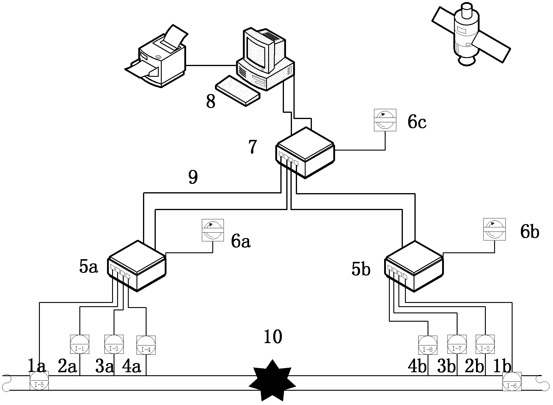
[0054] as attached figure 1 As shown, a gas pipeline leak detection and location device based on conventional data and acoustic signals includes sensor groups, on-site data acquisition processors (5a and 5b), central data collection processor 7, GPS receivers (6a, 6b and 6c), communication network 9 and monitoring host 8.

[0055] The first sensor group is composed of the acoustic wave sensor 4a, the pressure sensor 2a, the mass flow meter 1a and the temperature sensor 3a; the second sensor group is composed of the acoustic wave sensor 4b, the pressure sensor 2b, the mass flow meter 1b and the temperature sensor 3b. Install the first set of sensor sets at the beginning of the leak detection pipe section, and install the second set of sensor sets at the end of the leak detecti...


PUM


Abstract

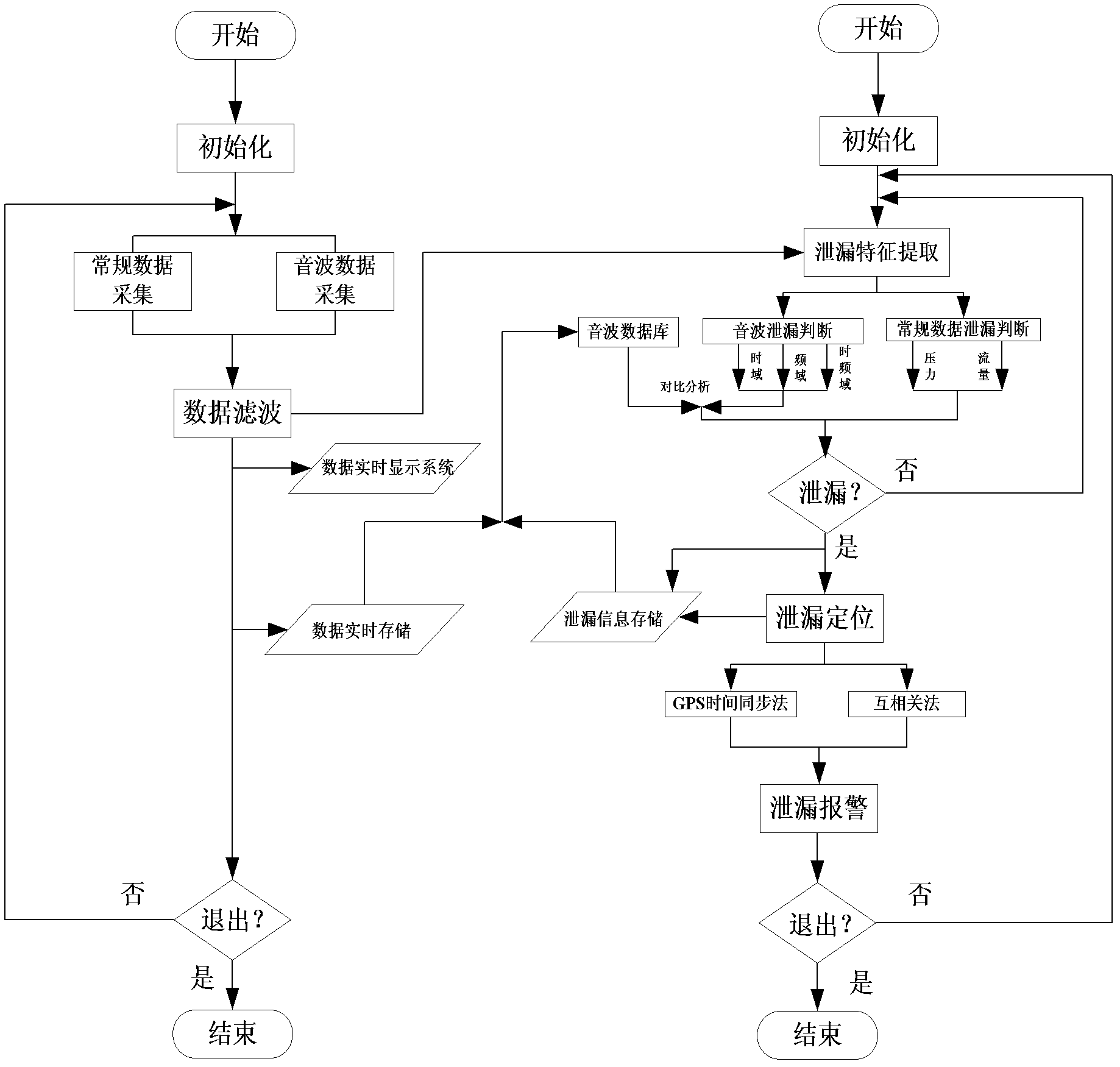
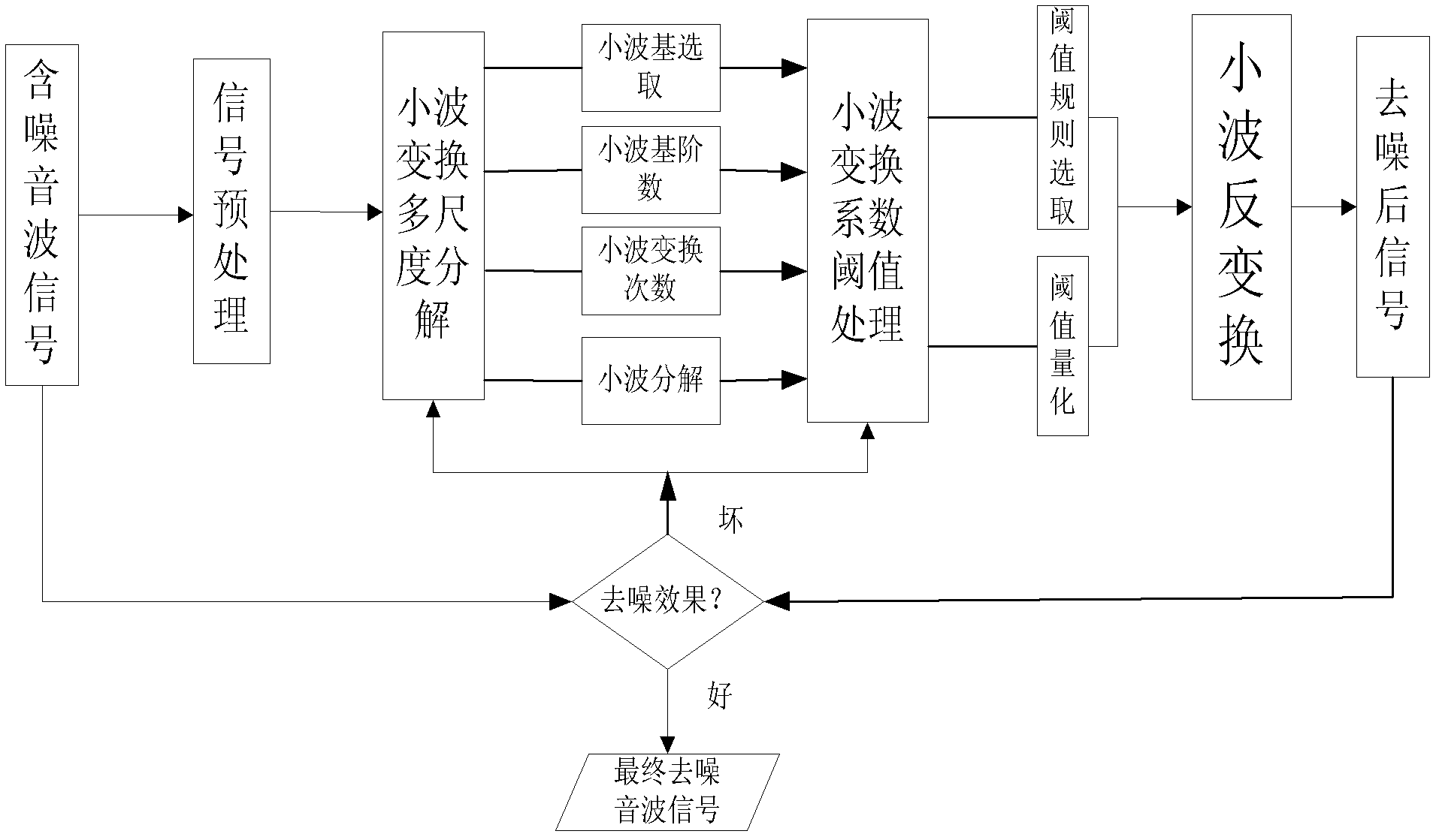
The invention discloses a device and a method for detecting and positioning leakage of a gas transmission pipeline based on conventional data and sound wave signals. The detecting device comprises a sensor group, a field data acquisition processor, a global positioning system (GPS) receiver, a communication network, a central data gathering processor and a monitoring host. The detecting method comprises the following steps of: respectively acquiring sound wave data and traffic, pressure and temperature conventional data of the upstream and the downstream of the pipeline, filtering background noise from the sound wave data by using wavelet transform, respectively identifying a time domain, a frequency domain and time and frequency domain characteristics of the sound wave signals by combining the conventional data to remove external interference and realize leakage signal characteristic extraction, performing leakage positioning by adopting an improved positioning method based on a related analysis method and a GPS synchronous time method, and giving a theoretical installation distance of sound wave sensors according to a propagation model of the sound wave signals. An interface can be established between the conventional data and a field supervisory control and data acquisition (SCADA) system, and only the sound wave sensors are arranged on the upstream and the downstream of the pipeline, so that the invention has the advantages of low investment, high equipment sensitivity and strong adaptability.

Description

Technical field: [0001] The invention relates to a pipeline leakage detection and positioning device and detection method, which belong to the technical field of gas transmission pipeline fault diagnosis and flow safety assurance. Accurately locate the location of the pipeline leak to ensure the safe production and operation of the gas pipeline. Background technique: [0002] According to the research on the current leak detection and location methods of gas pipelines at home and abroad, the leak detection and location methods are mainly concentrated in several aspects based on negative pressure wave method, transient model method, and acoustic leak detection method. The main domestic and foreign patents There are the following items. [0003] US Patent No. 6,389,881 discloses a pipeline leakage detection and location method based on the sonic method. The method captures the sound wave oscillation caused by the leakage, and eliminates external interference through the wave...

Claims


Application Information

Patent Timeline
IPC IPC(8): F17D5/02F17D1/02
Inventor 李玉星付俊涛王武昌孟令雅赵方生刘超刘翠伟彭红伟
Owner CHINA UNIV OF PETROLEUM (EAST CHINA)
Learn More