
Overburden water flowing fractured zone observation system and detection drilling method thereof

A water-conducting fissure zone and monitoring system technology, applied in seismology for well logging records, etc., can solve the problems of poor rigidity of the detection head, easy to produce misrecording or misrecording, and use, so as to avoid position errors and record Precise, less run-off effect

Inactive Publication Date: 2012-07-11
SHANDONG UNIV OF SCI & TECH
View PDF5 Cites 29 Cited by
  • Summary
  • Abstract
  • Description
  • Claims
  • Application Information

AI Technical Summary

Problems solved by technology

[0003] In the current detection equipment for double-end plugging water-conducting fissures in overlying rocks, such as CN101892841A, the detection head rod is a hollow structure, and the water inlet pipe is arranged inside the detection head rod. The detection head has poor rigidity and cannot be used on a drilling rig. When working, you need to use a drilling rig to drill out the detection hole, and then manually insert the detection head into the hole
Therefore, the position of the specific detection section is mainly measured and recorded manually. In the case of a bad underground environment, misrecording or misrecording is easy to occur, and when the inner wall of the detection hole has a slight collapse, the detection head may not be inserted manually. At this time, it is necessary to re-drill the hole, which is not only time-consuming and laborious, but also needs to find the detection position again, which greatly affects the detection work of the water-conducting fracture zone in the overlying rock

Method used


Image

  • Overburden water flowing fractured zone observation system and detection drilling method thereof
  • Overburden water flowing fractured zone observation system and detection drilling method thereof
  • Overburden water flowing fractured zone observation system and detection drilling method thereof

Examples


Embodiment Construction

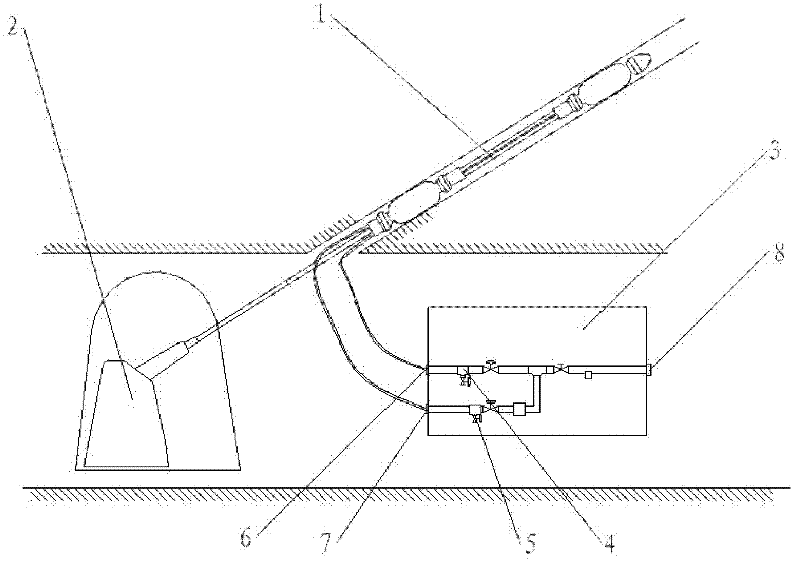
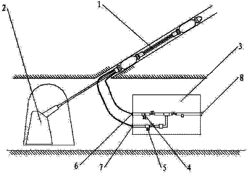
[0028] See attached figure 1 , which shows a monitoring system for a water-conducting fracture zone in overlying rock, including a drilling rig, a detection drilling device and a water injection control part.

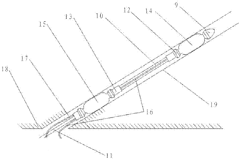
[0029] See attached figure 2 The detection and drilling device of the overburden water guiding fracture zone monitoring system includes a drill bit, a drill pipe and a connecting handle. The drill bit, drill pipe and connecting handle are all of solid structure. The drill bit is connected to the drill pipe through the first The connector is connected to the connection handle, where the drill bit can be a common coal seam drill bit, and the connection handle is used to connect the drilling machine. The diameter of the drill pipe is generally smaller than the minimum diameter of the first connector and the second connector, that is, it is screwed into the first connection connector and the second connector. The first connector and the second connector have ribs, and a ...


PUM


Abstract

An overburden water flowing fractured zone observation system comprises a drilling machine, a detection drilling device and a water-injection control section, wherein the detection drilling device comprises a drilling bit, a drilling rod and a connection handle, and the detection drilling device can be connected with the drilling machine through the connection handle; the detection drilling device further comprises plugging capsules, connectors and water inlet pipes, and the water inlet pipes can be connected with a hose connection of the water-injection control section. According to the overburden water flowing fractured zone observation system, the detection drilling device is directly arranged on the drilling machine which is used to send the detection device to a targeted position, accordingly, time saving and labor saving are achieved; a control system of the drilling machine is used to control the drilling of the detection drilling device, the controllability is good, the numerical value is accurate and the position error caused by manually placing the detection device is avoided; and with two pipes used for water injection and less water flowing out, the leakage is accurately recorded.

Description

technical field [0001] The invention relates to a coal mine device for detecting the development height of a water-guiding fissure zone in the overlying rock and a method for using the same, in particular to an automatic monitoring system for the height of the water-guiding fissure zone in the overlying rock and a method for detecting and drilling the same. Background technique [0002] In coal mines, especially in coal mine roofs with well-developed fracture zones, it is often necessary to use the method of water injection to measure leakage to detect the size of roof cracks, that is, to drill holes into the coal seam roof with special equipment, and to drill holes in a certain section of the hole. Water is injected into the roof, and the water penetrates into the roof through the cracks. When the water injection reaches saturation, the size of the cracks in the roof is judged according to the actual water injection volume, that is, the amount of leakage, so as to obtain the...

Claims


Application Information

Patent Timeline
Patent Type & Authority Applications(China)
IPC IPC(8): G01V1/40
Inventor 郭惟嘉张新国刘音李杨杨史俊伟江宁江兴元陈绍杰尹立明刘进晓常西坤孙文斌
Owner SHANDONG UNIV OF SCI & TECH
Learn More