Resonance tube and manufacture method of resonance tube, cavity filter
A manufacturing method and resonant tube technology, which can be used in the manufacture of resonators, waveguide devices, semiconductor/solid-state devices, etc., can solve the problems of high processing cost, high cost, compensation needs, and supply, etc., so as to reduce production costs and be suitable for use. performance, improve production efficiency
- Summary
- Abstract
- Description
- Claims
- Application Information
AI Technical Summary
Problems solved by technology
Method used
Image

Examples
Embodiment 1
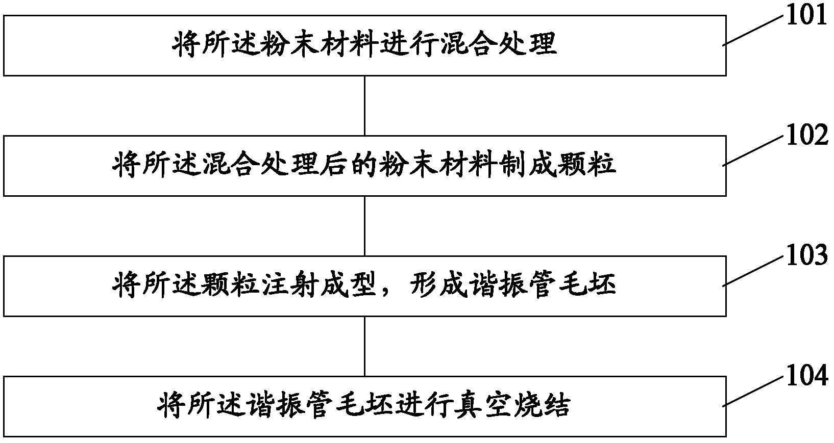
[0068] Embodiment 1 is a method for manufacturing a resonant tube in a cavity filter in the LTE (Long Term Evolution, long-term evolution technology) frequency band (2315-2375MHz), such as Figure 4 As shown, the method includes:
[0069] 201. Add the binder polypropylene and paraffin to the powder material containing 63% (mass percentage) of carbonyl iron powder and 37% (mass percentage) of carbonyl nickel powder, and mix well to form a paste , wherein the mass percentages of the powder material and the binder are 60-90% and 10-40%.
[0070] 202. Use a granulator to make the paste into strips or columns under the conditions of a working temperature of 150-300° C. and a working pressure of 5-10 MPa.
[0071] 203. Using an injection molding machine under the conditions of a working temperature of 200-300° C. and a working pressure of 40-50 MPa, inject and mold the particles to form a resonant tube blank.
[0072] Preferably, after the injection molding is completed, the mold ...
Embodiment 2
[0077] Embodiment 2 is at WiMax (Worldwide Interoperability for Microwave Access, global microwave interconnection access) 2.5GHz, the manufacturing method of the resonant tube in the filter that broadband is 20MHz, as Figure 5 As shown, the method includes:
[0078] 301. Add binder polypropylene and paraffin to the powder material containing 64% (mass percentage) of iron powder and 36% (mass percentage) of nickel powder, and mix uniformly to form a paste, wherein The mass percentages of the powder material and the binder are 60-90% and 10-40%.
[0079]302. Use a granulator to make the paste into strips or columns under the conditions of a working temperature of 210-250° C. and a working pressure of 7-10 MPa.
[0080] 303. Using an injection molding machine under the conditions of a working temperature of 250-300° C. and a working pressure of 40-50 MPa, inject and mold the particles to form a resonant tube blank.
[0081] Preferably, after the injection molding is completed...
Embodiment 3
[0086] Embodiment 3 is at TDD (Time Division Duplex, time division duplex) 2.0GHz, the manufacturing method of the resonant tube in the filter that broadband is 15MHz, as Figure 6 As shown, the method includes:
[0087] 401. Add binder poly Propylene and paraffin are mixed evenly to form a paste, wherein the mass percentages of the powder material and the binder are 60-90% and 10-40%.
[0088] 402. Use a granulator to make the paste into strips or columns under the conditions of a working temperature of 210-250° C. and a working pressure of 7-10 MPa.
[0089] 403. Using an injection molding machine under the conditions of a working temperature of 250-300° C. and a working pressure of 40-50 MPa, inject and mold the particles to form a resonant tube blank.
[0090] Preferably, after the injection molding is completed, the mold opening residence time is 3 seconds.
[0091] 404 . Vacuum sintering the resonant tube blank at a sintering temperature of 1300-1350° C. to form a sem...
PUM
| Property | Measurement | Unit |
|---|---|---|
| Particle size | aaaaa | aaaaa |
| Particle size | aaaaa | aaaaa |
| Particle size | aaaaa | aaaaa |
Abstract
Description
Claims
Application Information
 - R&D
- Intellectual Property
- Life Sciences
- Materials
- Tech Scout
- Unparalleled Data Quality
- Higher Quality Content
- 60% Fewer Hallucinations
Browse by: Latest US Patents, China's latest patents, Technical Efficacy Thesaurus, Application Domain, Technology Topic, Popular Technical Reports.
© 2025 PatSnap. All rights reserved.Legal|Privacy policy|Modern Slavery Act Transparency Statement|Sitemap|About US| Contact US: help@patsnap.com