Amplitude detection circuit with direct current offset elimination function

A DC offset and amplitude detection technology, applied in electrical components, transmission monitoring, transmission systems, etc.

Active Publication Date: 2012-07-11
杭州中科微电子有限公司
View PDF2 Cites 29 Cited by
  • Summary
  • Abstract
  • Description
  • Claims
  • Application Information

AI Technical Summary

Problems solved by technology

Contents of the invention

Method used


Image

  • Amplitude detection circuit with direct current offset elimination function
  • Amplitude detection circuit with direct current offset elimination function
  • Amplitude detection circuit with direct current offset elimination function

Examples


no. 1 example

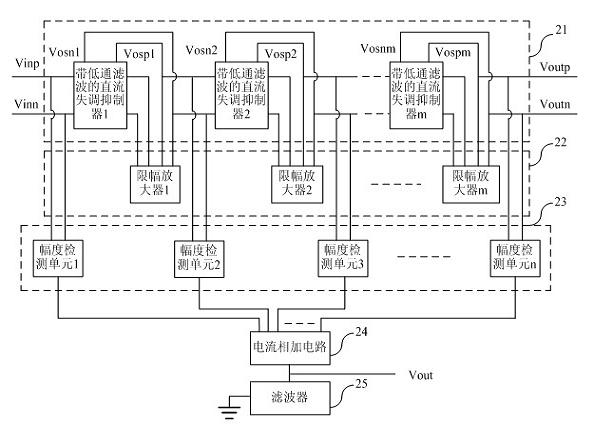
[0064] Figure 2a The block diagram of the amplitude detection circuit with the function of eliminating the DC offset according to the embodiment of the present invention is given. The amplitude detection circuit with DC offset cancellation function is composed of a DC offset suppression circuit 21 including an M-level DC offset suppressor with low-pass filtering, an amplitude limiting amplifier circuit 22 including an M-level limiting amplifier, and an N-level amplitude detection unit. The detection circuit 23 , the current addition circuit 24 and the filter 25 are constituted. The differential detection signal is connected to the differential input terminal of the amplitude detection circuit with the DC offset cancellation function, and is connected to the differential input terminal of the first-stage amplitude detection unit and the differential input terminal of the first-stage DC offset suppressor with low-pass filtering. The differential input terminal of the amplifier...

no. 2 example

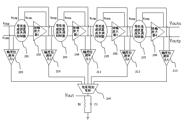
[0066] Figure 2b The block diagram of the amplitude detection circuit with the function of eliminating the DC offset according to the embodiment of the present invention is given. Set M to 4, and N=M+1. The amplitude detection circuit with the DC offset cancellation function of the embodiment includes the first-stage-fourth-stage DC offset suppressors 201, 203, 205 and 207 with low-pass filtering, the first-stage-fourth-stage limiting amplifier 202, 203 , 206 and 208 , the first to fifth stage amplitude detection units 209 , 210 , 211 , 212 and 213 , and the sum 208 , the current summing circuit 214 and the low-pass filtering circuit 215 . combine Figure 2b Describe the realization of the amplitude detection function in the present invention:

[0067] The differential input signals Vinn and Vinp are input to the first-stage DC offset suppressor 201 with low-pass filtering, and at the same time, they are subtracted from the low-pass filtered signal of the output of the cur...

no. 3 Embodiment

[0073] Image 6 The circuit diagram of another embodiment of the DC offset suppressor with low-pass filtering is given. Except for omitting the load tubes M8 and M9 connected by diodes, the circuit is basically the same as Image 6same.

[0074] The circuit includes two parts, a low-pass filter and a DC offset subtractor. The low-pass filter extracts the DC component in the data amplified by the next stage limiting amplifier. The low-pass filter is composed of an active resistor and a passive capacitor. The active resistor is realized by a multi-stage cascaded MOS tube working in the linear region. The resistance value of the resistor can be made very large, and the area occupied is relatively small. The value of the capacitance can be relatively small, so that both the resistance and the capacitance can be realized on the chip, which saves the cost of the chip. The subtraction of the input of the signal in the DC offset suppressor with low-pass filtering and the input of t...


PUM


Abstract

The invention discloses an amplitude detection circuit with a direct current offset elimination function. The amplitude detection circuit has a differential structure, and consists of a direct current offset elimination circuit, an amplitude limiting amplification circuit, an amplitude detection circuit, a current addition circuit and a filtering circuit, wherein the direct current offset elimination circuit comprises a plurality of direct current offset suppressors with a low-pass filtering function; the amplitude limiting amplification circuit comprises a plurality of amplitude limiting amplifiers; and the amplitude detection circuit comprises a plurality of amplitude detection units. A differential radio frequency signal is amplified to be saturated by a plurality of stages of cascaded amplitude limiting amplifiers, the output of each stage of amplitude limiting amplifier is detected by the amplitude detection units, output detected amplitude values are transmitted to the current addition circuit for addition, and the sum is filtered by the low-pass filtering circuit to obtain output voltage related to the amplitude of the input signal. The circuit can be adapted to the requirements of high monolithic integration level of a radio frequency chip, and is applied to a high-integration level zero-intermediate frequency receiver with the requirement of signal amplitude detection.

Description

Background technique [0001] In recent years, with the continuous emergence of new technologies in the field of information technology and the continuous advancement of technology, the signal strength of the input signal of the RF front-end of various receiver systems varies greatly, so it is necessary to pass the test under the premise of ensuring the bit error rate. The strength of the received signal is used to control the gain of the variable gain amplifier in order to control the power strength, avoid receiver saturation, and obtain a stable output signal strength. [0002] As we all know, modern systems have higher and higher requirements for system integration. At the same time, DC offset has become an inevitable problem in zero-IF receivers. However, the DC offset cancellation function of the prior art receiver system requires external components to obtain good performance. At the same time, the amplitude detection unit of the existing receiver generally adopts the str...

Claims


Application Information

Patent Timeline
Patent Type & Authority Applications(China)
IPC IPC(8): H04B17/00H04B17/21
Inventor 何晓丰
Owner 杭州中科微电子有限公司
Why Eureka
Try Eureka