Method for enhancing heat exchange of free surface array jet system

An array jet, free technology, applied in the direction of cooling/ventilation/heating transformation, can solve the problem of low heat exchange performance, and achieve the effect of improving heat exchange capacity, high heat exchange effect, and improving uniformity

Active Publication Date: 2012-07-11
NANJING UNIV OF SCI & TECH
View PDF2 Cites 3 Cited by
  • Summary
  • Abstract
  • Description
  • Claims
  • Application Information

AI Technical Summary

Problems solved by technology

[0005] The purpose of the present invention is to solve the problems of low heat transfer performance in the existing array jet technology, and provide a method that can be applied to heat dissipa

Method used


Image

  • Method for enhancing heat exchange of free surface array jet system
  • Method for enhancing heat exchange of free surface array jet system
  • Method for enhancing heat exchange of free surface array jet system

Examples


Embodiment 1

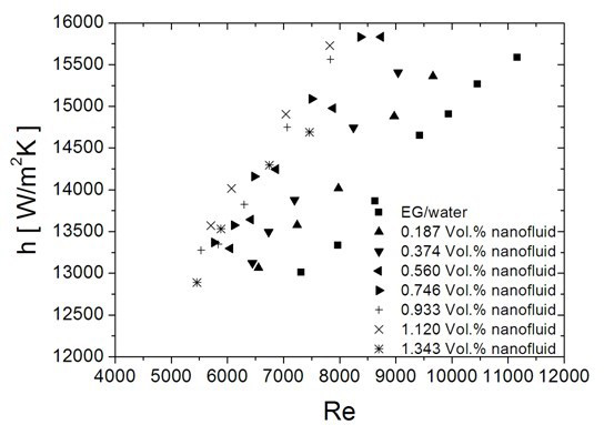
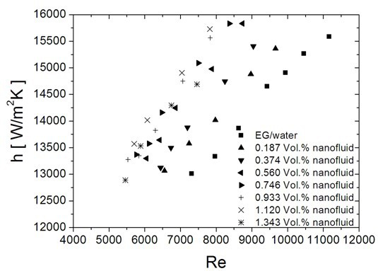
[0027] 1. Measure 1.5L each of ethylene glycol and deionized water, and mix them well to make a 1:1 ethylene glycol-water solution;

[0028] 2. Weigh 120g of metal copper nanoparticles with an average diameter of 50nm, add it to ethylene glycol-water solution, put it into an ultrasonic device for ultrasonication for 4h, and perform mechanical stirring at the same time to prepare copper-ethylene glycol with a volume fraction of 0.56%. Glycol-water nanofluid, which is a two-step method for preparing nanofluid;

[0029] 3. Optimize the system, heat-preserve the inside of the system tube, adjust the heat exchange equipment, select the diameter of the jet hole to be 1.5mm, the S / D to be 3, and the H / D to be 7; the surface is grooved, the groove depth is 0.5mm, and the groove width is 0.5mm , the groove spacing is 0.5mm, adjust the position of the jet hole to ensure that the array jet hole is facing the center of the heat exchange surface;

[0030] 4. Add the prepared nanofluid int...

Embodiment 2

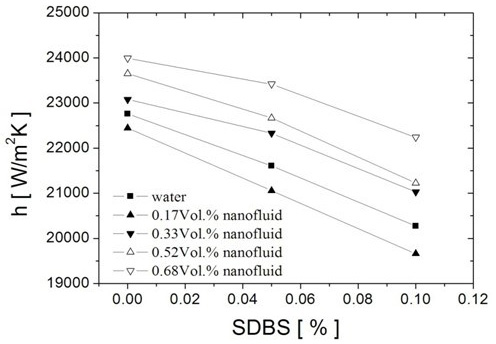
[0033] 1. Measure 3L of deionized water, weigh 38g of metal copper nanoparticles with an average diameter of 25nm, add it to deionized water, and add sodium dodecylbenzenesulfonate with a mass fraction of 0.05% as a dispersant at the same time, put it in Ultrasonic 4h in ultrasonic equipment, carry out mechanical stirring simultaneously, prepare the copper-water nanofluid that volume fraction is 0.17%;

[0034] 2. Optimize the system, heat-preserve the inside of the system tube, adjust the heat exchange equipment, select the jet hole diameter as 3.0mm, S / D as 1.5, and H / D as 5; the surface is grooved, the groove depth is 1.0mm, and the groove width is 0.5mm , the groove spacing is 0.5mm, adjust the position of the jet hole to ensure that the array jet hole is facing the center of the heat exchange surface;

[0035] 3. Add the prepared nanofluid into the experimental system, adjust the experimental temperature to 21°C, and the flow rate of the heat exchange working fluid to 0.2...

Embodiment 3

[0038] 1. Measure 3L of deionized water, weigh 79g of copper oxide nanoparticles with an average diameter of 50nm, add it to deionized water, and add 0.1% sodium dodecylbenzenesulfonate as a dispersant at the same time, put it in Ultrasonic 4h in ultrasonic equipment, carry out mechanical stirring simultaneously, prepare the copper oxide-water nanofluid that volume fraction is 0.33%;

[0039] 2. Optimize the system, heat-preserve the inside of the system tube, adjust the heat exchange equipment, select the jet hole diameter as 0.5mm, S / D as 10, and H / D as 15; the surface is grooved, the groove depth is 1.5mm, and the groove width is 2.0mm , the groove spacing is 2.0mm, adjust the position of the jet hole to ensure that the array jet hole is facing the center of the heat exchange surface;

[0040]3. Add the prepared nanofluid into the experimental system, adjust the experimental temperature to 20°C, the flow rate of the heat exchange working medium is 0.197m3 / h, and the simulat...


PUM


Abstract

Aiming at the problems of lower heat exchange performance and the like in the existing array jet technology, the invention provides a method capable of being applied to heat dissipation of electronic devices under a condition of high heating flux, so the heat dissipation capability of the electronic devices is improved and safe operation of the electronic devices is guaranteed. The method is characterized in that nano-fluid with high heat-conducting property is led into a free surface array jet system; and by selecting the metal/metal oxide nano-fluid with the high heat-conducting property and utilizing the high heat-conducting property and a heat exchange enhancing effect of the nano-fluid, the heat exchange capability of the array jet system is effectively improved and thereby a higher heat exchange effect is obtained. Compared with the prior art, the method has the remarkable advantages that 1, the nano-fluid used as an experimental working medium has higher heat-conducting property than an ordinary working medium; 2, random motion of nano-particles in the nano-fluid is beneficial to heat transfer in the fluid, so the improvement of the uniformity of surface temperature of a heating body can be benefited; and 3, a heat exchange surface is impacted by the nano-particles in the nano-fluid, so the heat exchange capability of the free surface array jet system is improved.

Description

technical field [0001] The invention belongs to a heat control method for an electronic device, which introduces a nanofluid with high thermal conductivity into a free surface array jet, thereby effectively enhancing the heat exchange effect of the array jet. Background technique [0002] The principle of jet impingement cooling is: the fluid is directly sprayed to the surface to be cooled through a nozzle of a certain shape (circular or slit shape). Due to the short flow and high flow rate, a large pressure is formed on the heat exchange surface, and the jet impacts the stagnation point. The boundary layer near the cooling zone becomes very thin, so it has extremely high heat transfer efficiency. Compared with conventional convective heat transfer technology, the impact heat transfer coefficient of jet cooling technology is several times or even an order of magnitude higher. Reference 1 (Fabbri Metteo, Dhir Vijay K., Optimized heat transfer for high power electronic cooling...

Claims


Application Information

Patent Timeline
IPC IPC(8): H05K7/20
Inventor 宣益民李强铁鹏
Owner NANJING UNIV OF SCI & TECH
Why Eureka
Try Eureka