Oil-water separation process of pulpifying centrifugal treatment system

A technology of centrifugal treatment and oil-water separation, which is used in energy and wastewater treatment, water/sewage multi-stage treatment, water/sludge/sewage treatment, etc. It can improve the oil concentration, reduce the production of biogas residue, and avoid re-consumption.

Active Publication Date: 2012-07-18
NINGBO KASEEN ECOLOGY TECHNOLOGY CO LTD
View PDF7 Cites 8 Cited by
  • Summary
  • Abstract
  • Description
  • Claims
  • Application Information

AI Technical Summary

Problems solved by technology

[0004] In the prior art, as the patent No. is CN201120139561.1 Chinese invention application patent "kitchen waste oil-water separation treatment method" (announcement number is CN202038949U); The first steam heater, three-phase horizontal centrifuge, oil separation pool, second steam heater, vertical centrifuge, waste material storage filter, sedimentation tank, conical recovery container with a tip at the lower end, membrane bioreaction pool and oil-water separation tank for oil-water separation treatment; this technology uses secondary centrifugal method for oil-water separation, the temperature interval between the two is relatively large, and the oil-water separation is not complete, even if there is a lot of oil, it will be easily flowed away, which is not conducive to Improve the recovery rate; some liquid and solid materials produced during the oil-water separation process do not involve corresponding follow-up treatment measures

Method used


Image

  • Oil-water separation process of pulpifying centrifugal treatment system
  • Oil-water separation process of pulpifying centrifugal treatment system

Examples


Embodiment Construction

[0023] The present invention will be further described in detail below in conjunction with the accompanying drawings and embodiments.

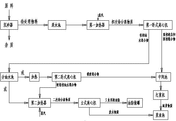
[0024] Such as figure 1 As shown, the embodiment of the present invention is an oil-water separation process of a slurry centrifugal treatment system. The slurry centrifugal treatment system includes a beater, a sand settler, a horizontal centrifuge, a heater, a vertical centrifuge and a slurry tank , the oil-water separation process includes the following steps:

[0025] Preparation steps: prepare a raw material containing oil and fat, and the raw material has been crushed and screened in advance;

[0026] Sand settling and impurity removal step: Put the raw materials into the sand settler one after another. There are partition chambers arranged side by side in a straight line in the middle of the sand chamber; the raw materials are divided into two parts after being filtered by the partition chamber: one part is impurities, and the other pa...


PUM

PropertyMeasurementUnit
diameteraaaaaaaaaa

Abstract

The invention discloses an oil-water separation process of a pulpifying centrifugal treatment system. The pulpifying centrifugal treatment system comprises a pulp beater, a sand settling device, a horizontal centrifuge, a heater, a vertical centrifuge and a pulp tank. The oil-water separation process comprises the steps as follows: a preparation step, a primary heating step, a primary centrifugation step, a secondary heating step, a secondary centrifugation step and a hydration and pulp-beating step. Hydrated beaten pulp continuously and mutually collides with wear-resistant material in the equipment at a high speed and is ground into thickened pulp material, so that the digestion rate of a back-section anaerobic fermentation system and the biogas yield are increased; a secondary centrifugation step is added, so that the design flow of the oil-water separation process is reasonable, the next step vertical centrifugation effect is facilitated, and the outlet oil concentration and the operation efficiency are increased; a good centrifugal oil outlet effect is achieved, and the water content of obtained thick oil and the oil content of wastewater material are low; and the back-section anaerobic fermentation efficiency is improved, oil-water separation of the material is conducted more thoroughly and re-consumption of energy is avoided.

Description

technical field [0001] The invention relates to the technical field of oily water treatment in solid waste, in particular to an oily water separation process of a slurry centrifugal treatment system. Background technique [0002] Food waste mainly refers to food waste produced by households, canteens, catering industries, etc., commonly known as swill, which is an important part of urban garbage; in view of our country's diet, the amount of food waste is huge; because food waste contains many organic matter Once the food waste rots and deteriorates, the harm it will cause is immeasurable. The main components of kitchen waste include rice and flour food residues, vegetables, animal and vegetable oils, meat, bones, etc. In terms of chemical composition, they include starch, cellulose, protein, lipids, and inorganic salts. Kitchen waste is characterized by rich organic matter content, high moisture content, and perishability. If it is not disposed of in a timely and reasonable...

Claims


Application Information

Patent Timeline
Patent Type & Authority Applications(China)
IPC IPC(8): C02F9/10
CPCY02W10/33
Inventor 朱豪轲朱华伦沈炳国王能杰吴方亮胡代平
Owner NINGBO KASEEN ECOLOGY TECHNOLOGY CO LTD
Why Eureka
Try Eureka