

Portable multifunctional vacuum calibration system and method
A calibration system and multi-functional technology, applied in the field of measurement, can solve the problems of high cost of magnetic levitation rotor gauge, inability to meet the needs of on-site vacuum leak calibration, complex and huge system, etc.
- Summary
- Abstract
- Description
- Claims
- Application Information
AI Technical Summary
Problems solved by technology
Method used
Image

Examples
Embodiment 1
[0044] The steps for calibrating the vacuum leak hole 7 to be calibrated by using the above-mentioned device are as follows:
[0045] S11. Install the vacuum leak hole 7 to be calibrated on the third vacuum valve 8, and check the tightness of the installation;
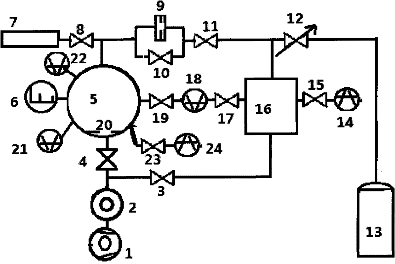
[0046] S12, turn on the mechanical pump 1, the first vacuum valve 3, the second vacuum valve 4, the fourth vacuum valve 10, the fifth vacuum valve 11, the ninth vacuum valve 15, the sixth vacuum valve 17, and the seventh vacuum valve 19 in sequence, Evacuate the calibration chamber 5, the plenum chamber 16 and each valve pipeline, open the second vacuum gauge 18, and keep the ambient temperature range at 23±3°C, when the pressure in the plenum chamber measured by the second vacuum gauge 18 is less than 20Pa , start molecular pump 2;
[0047] S13, when the vacuum degree in the plenum chamber 16 is less than 130Pa, open the ninth vacuum valve 15 and the first vacuum gauge 14, when the vacuum degree in the calibration ch...
Embodiment 2
[0058] The steps for calibrating the vacuum gauge 22 to be calibrated by using the above-mentioned device are as follows:
[0059] S21, install the vacuum gauge 22 to be calibrated on the calibration chamber 5, and check the tightness of the installation;
[0060] S22, turn on the mechanical pump 1, the first vacuum valve 3, the second vacuum valve 4, the fourth vacuum valve 10, the fifth vacuum valve 11, the ninth vacuum valve 15, the sixth vacuum valve 17, the seventh vacuum valve 19, The eighth vacuum valve 23 pumps air to the calibration chamber 5, the plenum chamber 16 and the valve pipes, opens the second vacuum gauge 18, and keeps the ambient temperature at 23±3°C. When the second vacuum gauge 18 measures to the plenum chamber When the pressure in 16 is less than 20Pa, start the molecular pump 2;
[0061] S23, open the third capacitance gauge 21, when the vacuum degree in the plenum chamber 16 is less than 130Pa, open the ninth vacuum valve 15 and the first vacuum gaug...
PUM
 Abstract
Description
Claims
Application Information