Distributed three-phase four-wire photovoltaic grid-connected device with electric energy adjusting function

A three-phase four-wire, distributed technology, used in photovoltaic power generation, harmonic reduction devices, and multi-phase network asymmetry reduction, etc. The grid-connected current will pollute the power grid and other problems, so as to achieve the effect of eliminating pollution.

Inactive Publication Date: 2012-07-18
HEILONGJIANG ELECTRIC POWER RES INST +1
View PDF5 Cites 13 Cited by
  • Summary
  • Abstract
  • Description
  • Claims
  • Application Information

AI Technical Summary

Problems solved by technology

[0003] The present invention aims to solve the problem that the existing device cannot compensate the reactive component, harmonic component and unbalanced component generated by the user's electric load, and cannot eliminate the pollution of the grid-connected current of these components to the grid. Distributed three-phase four-wire photovoltaic grid-connected device with power adjustment function

Method used


Image

  • Distributed three-phase four-wire photovoltaic grid-connected device with electric energy adjusting function
  • Distributed three-phase four-wire photovoltaic grid-connected device with electric energy adjusting function
  • Distributed three-phase four-wire photovoltaic grid-connected device with electric energy adjusting function

Examples


specific Embodiment approach 1

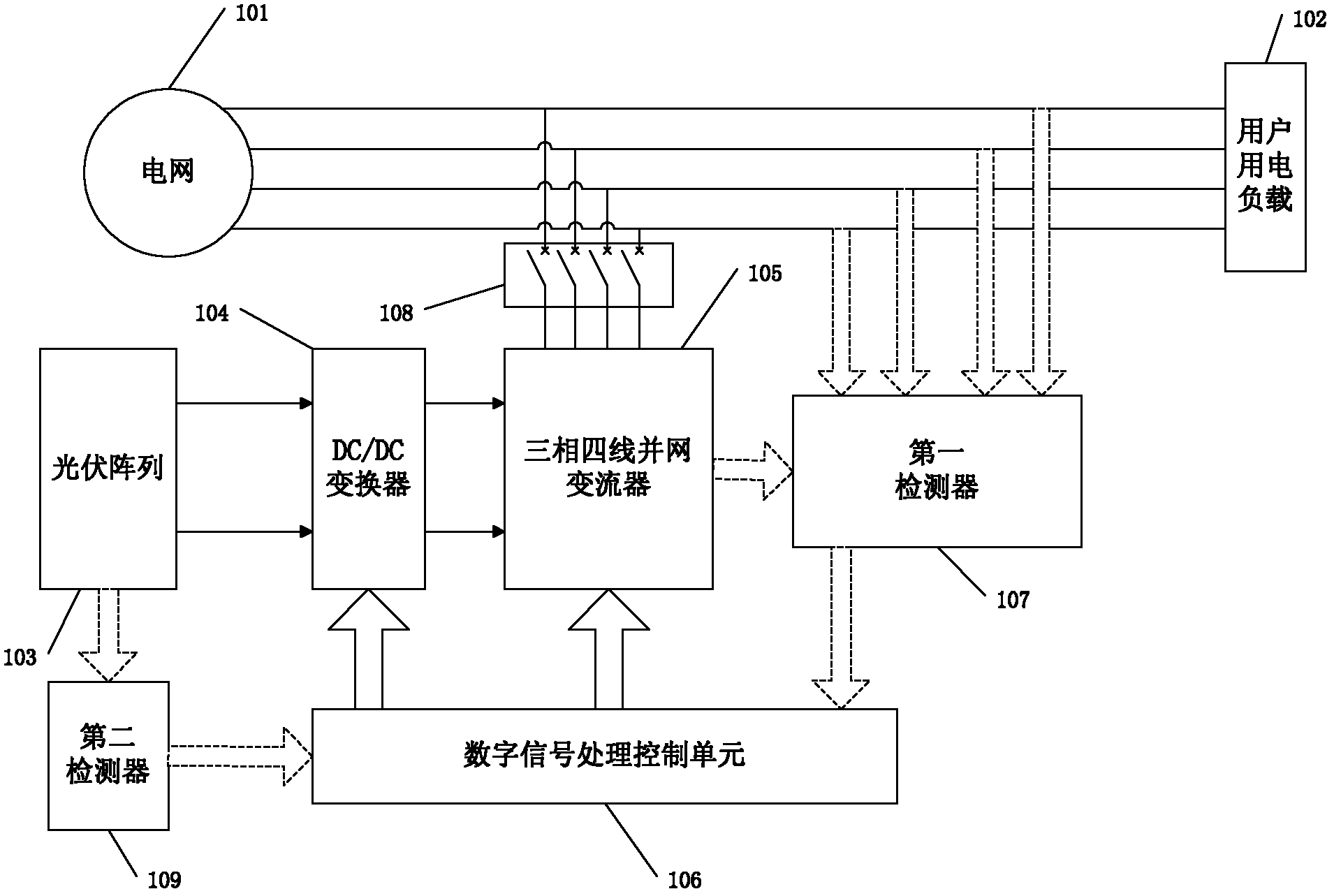
[0007] Specific implementation mode 1. Combination figure 1 Describe this embodiment, a distributed three-phase four-wire photovoltaic grid-connected device with power adjustment function, which includes a power grid 101, user power load 102, photovoltaic array 103, DC / DC converter 104, three-phase four-wire Grid-connected converter 105, digital signal processing control unit 106, circuit breaker 108, first detector 107 and second detector 109, DC voltage output terminal of photovoltaic array 103 and DC voltage input terminal of DC / DC converter 104 The DC voltage output terminal of the DC / DC converter 104 is connected to the DC voltage input terminal of the three-phase four-wire grid-connected converter 105, and the three-phase voltage on the AC side of the three-phase four-wire grid-connected converter 105 The output end is connected to the power grid 101 through the circuit breaker 108, the DC power conversion control signal output end of the digital signal processing contro...

specific Embodiment approach 2

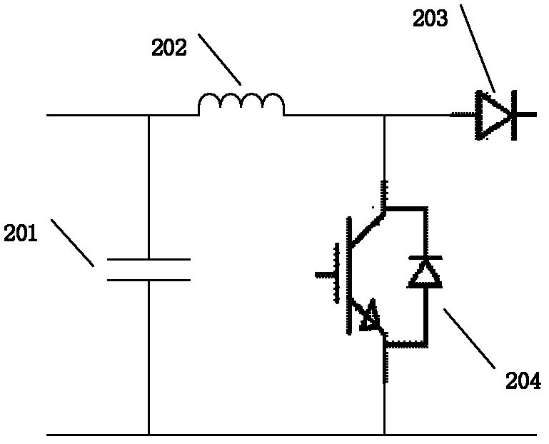
[0008] Specific embodiment two, combine figure 2 Describe this embodiment, the difference between this embodiment and specific embodiment 1 is: the DC / DC converter 104 includes a DC capacitor 201, a freewheeling inductor 202, a power diode 203 and a fully-controlled power device IGBT204, and the DC / DC conversion The DC voltage input terminal of the device 104 is connected in parallel with a DC capacitor 201, one end of the DC capacitor 201 is connected with one end of the freewheeling inductor 202, and the other end of the freewheeling inductor 202 is simultaneously connected with the collector of the fully-controlled power device IGBT204 and the collector of the power diode 203 The anodes are connected, the cathode of the power diode 203 is used as a DC voltage output terminal of the DC / DC converter 104, and the emitter of the fully-controlled power device IGBT204 is connected to the other end of the DC capacitor 201, and serves as the DC / DC converter 104 The other DC voltag...

specific Embodiment approach 3 pic 3 Embodiment approach , Embodiment approach and specific Embodiment approach 1 : 3 4 105301、 4 302、303、LC306,LC306 4 304 and 4 305, 4 302 4 4 IGBT, no. 1 IGBT and no. 2 IGBT and 1 304 1 ,304 1 and 1 305 1 ,305 1 , 3 4 105301,301 1 and no. 1 IGBT,301 1 and no. 2 IGBT,106PWM and 303PWM,303 4 and 4 302 4 。 specific Embodiment approach 4

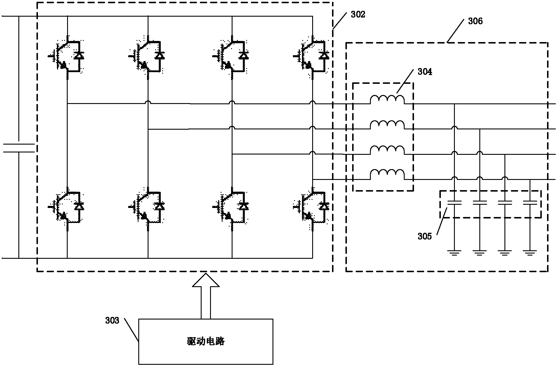
[0010] Specific embodiment three, combine image 3 This embodiment is described. The difference between this embodiment and the first embodiment is that the three-phase four-wire grid-connected converter 105 includes a DC side capacitor 301, a four-arm voltage source converter 302, a driving circuit 303, an LC type filter output circuit 306, the LC type filter output circuit 306 includes four filter output circuit inductances 304 and four filter output circuit capacitors 305, and the four bridge arms of the four-arm voltage source converter 302 are composed of four pairs of fully-controlled power device IGBT, the emitter of the first fully-controlled power device IGBT of each bridge arm is connected to the collector of the second fully-controlled power device IGBT and one end of a filter output circuit inductor 304 at the same time, each filter output circuit The other end of the inductance 304 is respectively connected to one end of a filter output circuit capacitor 305, the ...


PUM


Abstract

The invention provides a distributed three-phase four-wire photovoltaic grid-connected device with an electric energy adjusting function, belonging to the technical field of a multifunctional photovoltaic grid-connected device and aiming to solve the problem that the conventional device cannot compensate an idle component, a harmonic component and an unbalanced component which are generated by a user electricity load and cannot remove pollution on a power grid caused by grid-connected currents of the components. The distributed three-phase four-wire photovoltaic grid-connected device comprises the power grid, the user electricity load, a photovoltaic array, a DC (Direct Current)/DC converter, a three-phase four-wire grid-connected inverter, a digital signal processing control unit, a circuit breaker, a first detector and a second detector. The first detector is used for detecting the output-phase current at the alternating current side of the three-phase four-wire grid-connected inverter and the input voltage and the input current of the user electricity load; and the second detector is used for detecting the output voltage and the output current of the photovoltaic array. According to the invention, the photovoltaic grid-connected device which is used for production and scientific research of multidirectional development of solar energy sources and is particularly applicable to a photovoltaic grid-connected generation device which is combined with buildings and is connected into the power grid in a three-phase four-wire manner is provided.

Description

technical field [0001] The invention belongs to the technical field of multifunctional photovoltaic grid-connected devices, and in particular relates to a distributed three-phase four-wire photovoltaic grid-connected device with the function of electric energy regulation. Background technique [0002] At present, the known distributed three-phase four-wire photovoltaic grid-connected device is composed of a solar photovoltaic array, a DC / DC converter, a grid-connected inverter, a grid-connected power generation controller and corresponding protection. Under the irradiation of sunlight, the distributed three-phase four-wire photovoltaic grid-connected device uses the photovoltaic effect to directly convert solar radiation energy into electrical energy and connects it to the grid. In addition to powering the user's electrical load, the excess electrical energy can be fed into the grid. When the light intensity is insufficient at night or in rainy days, the power generated by ...

Claims


Application Information

Patent Timeline
Patent Type & Authority Applications(China)
IPC IPC(8): H02J3/38H02J3/18H02J3/01H02J3/26
CPCY02E40/50Y02E10/563Y02B10/14Y02E40/30Y02B10/10Y02E10/56Y02E40/40
Inventor 祖光鑫贾长阁沈向东
Owner HEILONGJIANG ELECTRIC POWER RES INST
Why Eureka
Try Eureka