Dynamic magnetic resonance imaging method and system

A dynamic imaging, magnetic resonance imaging technology, applied in medical science, sensors, diagnostic recording/measurement, etc., can solve the problems of slow imaging speed, image blur, image motion artifacts, etc., to improve imaging speed, good effect, reduce effect of data

Active Publication Date: 2012-07-25
SHENZHEN INST OF ADVANCED TECH CHINESE ACAD OF SCI
View PDF3 Cites 3 Cited by
  • Summary
  • Abstract
  • Description
  • Claims
  • Application Information

AI Technical Summary

Problems solved by technology

[0003] Although magnetic resonance imaging has many advantages such as good soft tissue resolution, multi-directional and multi-parameter imaging, and no X-ray radiation damage, but due to the limitation of its imaging technology, most imaging methods of magnetic resonance imaging require a long scan time. For example, it takes between 15 and 30 seconds to acquire a classical spin echo image
The slow imaging speed greatly limits the image time resolution of magnetic resonance imaging in dynamic imaging, and at the same time, it will produce serious motion artifacts in the image, reduce the image quality, and affect clinical diagnosis, which severely limits magnetic resonance imaging. Applications in the fields of heart, coronary artery and other moving organs and nerve function imaging
In the magnetic resonance dynamic imaging of moving organs such as the heart and coronary arteries, the imaging speed is slow, and the physiological movement of the subject's body during the imaging process will blur the image and distort the contrast, which cannot meet the requirements of dynamic imaging of the heart, brain, etc. Requirements for rapid imaging such as functional imaging, human motion imaging, and real-time navigation

Method used


Image

  • Dynamic magnetic resonance imaging method and system
  • Dynamic magnetic resonance imaging method and system
  • Dynamic magnetic resonance imaging method and system

Examples


Embodiment Construction

[0022] In order to solve the problem that the imaging speed is slow in traditional magnetic resonance dynamic imaging, and the physiological movement of the subject's body during the imaging process will make the image blurred, the contrast will be distorted, and it cannot meet the requirements of fast imaging such as cardiac dynamic imaging. A magnetic resonance dynamic imaging method with fast imaging speed to realize fast imaging.

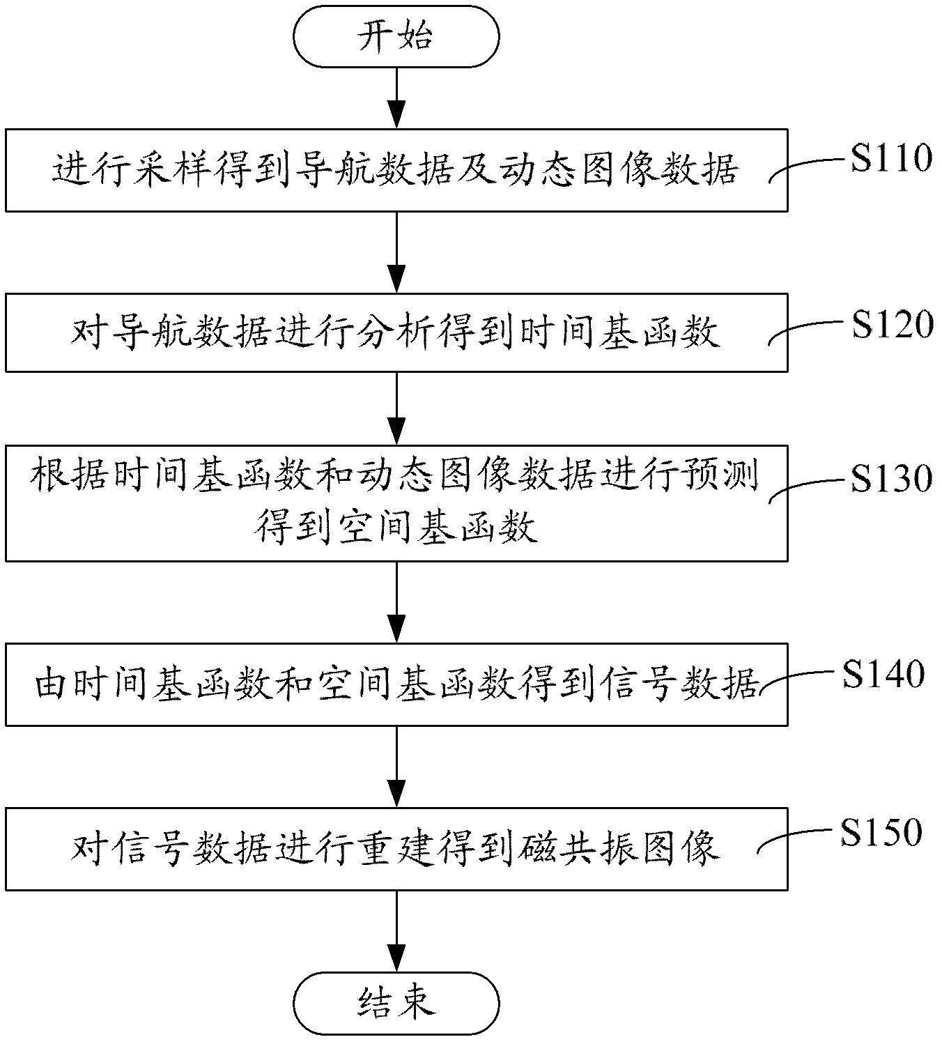
[0023] see figure 1 , a magnetic resonance dynamic imaging method, comprising the following steps:

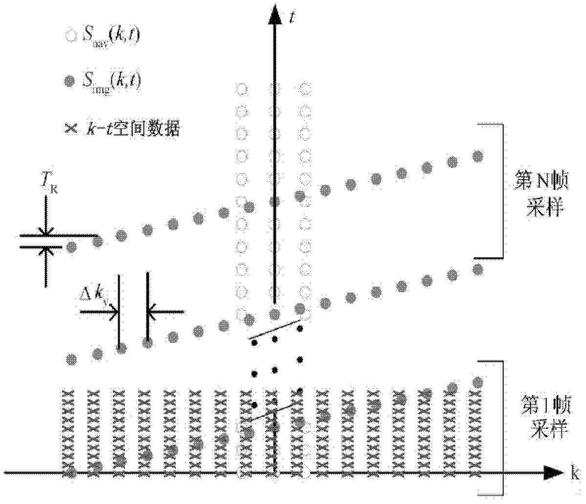
[0024] Step S110, sampling to obtain navigation data and dynamic image data. Sampling the data of the object to be imaged. In the magnetic resonance dynamic imaging of a moving object, the actually received signal data is S(k, t), where k represents space and t represents time. The actual image ρ(r, t) is a function of its spatial position variable r and time variable t. Considering Fourier imaging, the relationship between the actual receive...


PUM


Abstract

A dynamic magnetic resonance imaging method is characterized by including following steps: sampling to obtain navigation data and dynamic image data; analyzing the navigation data to obtain a temporal basis function; predicting according to the temporal basis function and the dynamic image data so as to obtain a spatial basis function; obtaining signal data according to the temporal basis function and the spatial basis function; and rebuilding the signal data to obtain a magnetic resonance image. Complex image data for a dynamic image are separated into the temporal basis function and the spatial basis function, only the navigation data with high temporal resolution and low spatial resolution and the dynamic image data with high spatial resolution and low temporal resolution are acquired to realize complementation, the data required to be acquired are reduced, and dynamic magnetic resonance imaging speed is increased to a great extent. Besides, the invention further provides a dynamic magnetic resonance imaging system.

Description

【Technical field】 [0001] The invention relates to magnetic resonance technology, in particular to a magnetic resonance dynamic imaging method and system. 【Background technique】 [0002] In 1971, American scientist Paul Lauterbur proposed MRI (Magnetic Resonance Imaging, MRI) and published the first MRI experiment results in 1973. After more than 30 years of development, magnetic resonance imaging has become one of the important means of clinical medical examination, providing very valuable diagnostic information for clinical medicine. Compared with other medical imaging technologies, magnetic resonance imaging technology has the advantages of no radiation hazard, multi-directional and multi-parameter imaging. Some physiological and biochemical information. [0003] Although magnetic resonance imaging has many advantages such as good soft tissue resolution, multi-directional and multi-parameter imaging, and no X-ray radiation damage, but due to the limitation of its imaging...

Claims


Application Information

Patent Timeline
IPC IPC(8): A61B5/055
Inventor 梁栋冯翔刘新郑海荣谢国喜
Owner SHENZHEN INST OF ADVANCED TECH CHINESE ACAD OF SCI
Why Eureka
Try Eureka