Miniaturized bifunctional line electrode grinding device

A wire electrode grinding, dual-function technology, applied in the direction of grinding machine parts, grinding/polishing equipment, grinding machines, etc., can solve the problems of increasing the overall size of the machine tool, reducing the operating space of the machine tool, and large use space, etc. Achieve the effect of expanding comprehensive processing capacity, simple and compact structure and layout, and realizing space size

Inactive Publication Date: 2012-07-25
INST OF MACHINERY MFG TECH CHINA ACAD OF ENG PHYSICS
View PDF5 Cites 9 Cited by
  • Summary
  • Abstract
  • Description
  • Claims
  • Application Information

AI Technical Summary

Problems solved by technology

At present, the wire electrode grinding mechanism of typical domestic and foreign micro-electric processing machine tools generally adopts the structure of wire receiving wheel + counterweight + wire outlet wheel. The space size is large and the weight is heavy, which restricts the wire electrode grinding workbench The dynamic characteristics of the movement affect the machining accuracy of the micro-electric machining machine tool; and the huge wire electrode grinding mechanism occupies a large space, which will inevitably reduce the operating space of the machine tool, which is unfavorable to the operation convenience of the machine tool, and even for the This occupies the space of other parts of the machine tool and increases the overall size of the machine tool
In addition, the area size of the tool electrode processed by the traditional wire electrode grinding mechanism is fixed and cannot be adjusted, which can only meet the processing requirements of a single type of tool electrode, and the function is limited, which limits the application range of the wire electrode grinding device

Method used


Image

  • Miniaturized bifunctional line electrode grinding device
  • Miniaturized bifunctional line electrode grinding device
  • Miniaturized bifunctional line electrode grinding device

Examples


Embodiment

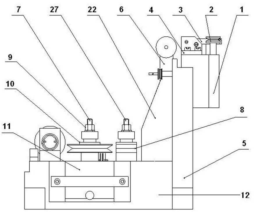
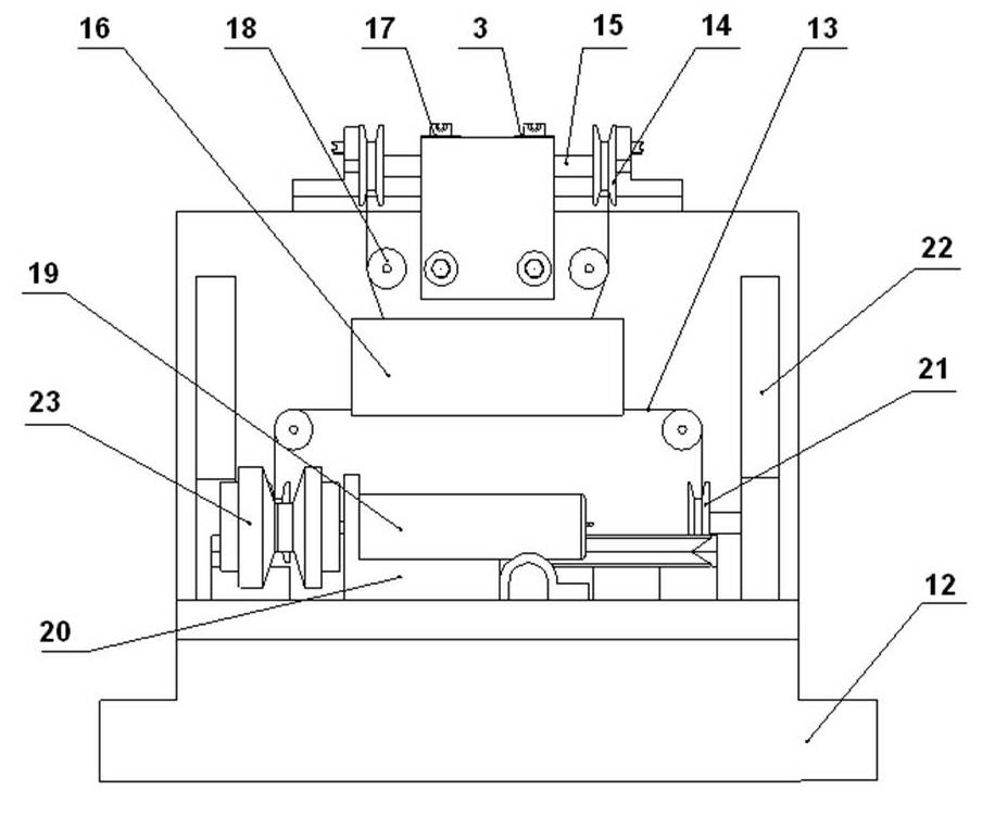
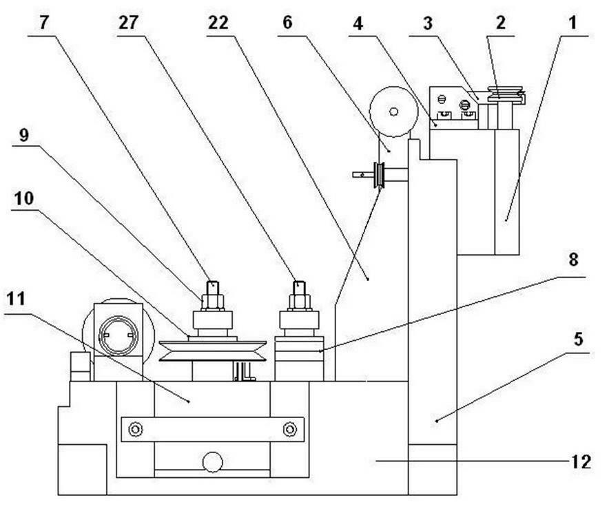
[0021] figure 1 It is a front view of a miniaturized dual-function wire electrode grinding device of the present invention, figure 2 It is a side view of a miniaturized dual-function wire electrode grinding device of the present invention. exist figure 1 , figure 2 Among them, the miniaturized dual-function wire electrode grinding device of the present invention includes a grinding head base 1, a fixed wheel 2, a right grinding head 3, a screw support 4, a supporting vertical plate 5, an upper transition wheel hanging plate 6, Support nail Ⅰ7, support nail Ⅱ 27, damping plate 8, set nut 9, wire outlet wheel 10, damper 11, support base plate 12, upper transition wheel 14, adjusting screw 15, shock absorber 16, left grinding head 17, Guide wheel 18, motor assembly 19, motor seat 20, lower transition wheel 21, reinforcing plate 22, wire receiving wheel 23; Its connection relation is, described adjusting screw rod 15 is assembled on the screw rod support 4 and can rotate free...


PUM


Abstract

The invention discloses a miniaturized bifunctional line electrode grinding device. A motor assembly, a wire winding wheel, a wire discharging wheel, a damper and a damping fin in the line electrode grinding device are arranged on a bottom supporting plate, and a left grinding head, a right grinding head, a shock absorber, a guide wheel and a transition wheel are arranged on a vertical supporting plate. An electrode wire is wound on the left grinding head and the right grinding head after being led out by the wire discharging wheel and passing through a middle transition device and then passes through corresponding transition devices, and finally, wire winding is realized by the wire winding wheel, so that the whole wire moving process is finished. The motor assembly drives the wire winding wheel to rotate to realize the wire moving function of the electrode wire. All the devices provided by the invention are arranged reasonably, the device can be miniaturized and lightened, and the dynamic characteristic of a workbench can be improved. The spatial size of an electric discharge machining region arranged between the left grinding head and the right grinding head provided by the invention can be flexibly adjusted, the machining requirements of a microarray tool electrode and a non-microarray tool electrode can be met, and the function of a micro-electric machining system is remarkably expanded.

Description

technical field [0001] The invention belongs to the field of micro-high-efficiency electrical machining, and in particular relates to a miniaturized dual-function wire electrode grinding device, which can realize the processing of array-type micro-tool electrodes, and can also realize the processing of non-array-type micro-tool electrodes. Background technique [0002] With the development of science and technology, various micromachines and microelectromechanical systems are becoming increasingly miniaturized, thus proposing a large number of manufacturing requirements for parts with tiny features (such as holes, slots, slots, and complex tiny three-dimensional cavities). Higher requirements are put forward for microfabrication technology. Due to the characteristics of non-contact, no macroscopic cutting force, and wide application range of materials, micro-electromachining technology has incomparable advantages in the field of micro-featured parts processing, and its deman...

Claims


Application Information

Patent Timeline
Patent Type & Authority Applications(China)
IPC IPC(8): B24B19/00B24B41/04
Inventor 张勇斌王新宽吉方何建国吴祉群刘广民刘坤雷艳华鱼胜利朱建平
Owner INST OF MACHINERY MFG TECH CHINA ACAD OF ENG PHYSICS
Why Eureka
Try Eureka