Comparison type calibration method for dynamic measurement system
A calibration method and dynamic measurement technology, applied in the field of data correction, which can solve the problems of inconsistent speed sources, inability to measure values, transmission and traceability, etc.
- Summary
- Abstract
- Description
- Claims
- Application Information
AI Technical Summary
Problems solved by technology
Method used
Image
Examples
Embodiment 11
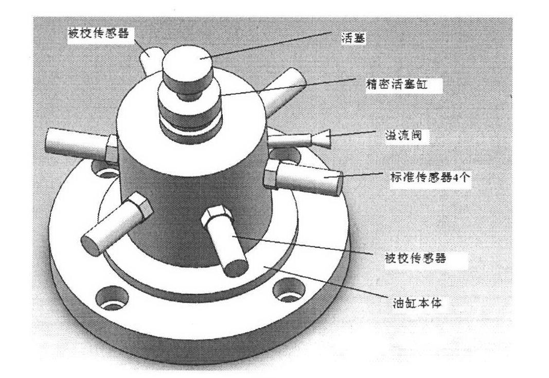
[0041] combine figure 1 , this example corrects the data of the comparative calibration based on the dynamic pressure measurement system based on the drop weight, and the specific implementation steps are as follows:
[0042] 1) if figure 1 As shown, the drop hammer hydraulic dynamic marking device is composed of a piston, a precision piston cylinder, an overflow valve, and a cylinder body. Four standard sensors (I, II, III, IV) and two sensors to be marked are installed around the precision piston cylinder. (X, Y). The free-falling weight converts the gravitational potential energy into kinetic energy, and then collides with the precision piston on the top of the cylinder. The liquid in the cylinder is compressed by the piston to generate pressure in the cylinder, thereby converting the kinetic energy of the weight into the elasticity of the volume deformation of the hydraulic oil. potential energy. When the kinetic energy is fully converted, the weight and the piston reac...
Embodiment 12
[0052] Based on the data of the comparison calibration of the dynamic pressure measurement system of the drop hammer, the experimental device is still the drop hammer hydraulic dynamic standard device, and two standard sensors and a compared sensor Z are installed around the precision piston cylinder. According to the above experiment The operating procedures are used to carry out experiments, and the experimental data and processing results are shown in Tables 4 and 5.
[0053] Table 4 Dynamic Calibration Test Data
[0054]
[0055]
[0056] Table 5 Evaluation of pressure data measurement results
[0057]
[0058]The calculation of the 4 data shows that there is an obvious deviation between the pressure sources monitored by the standard sensor multiple times during calibration, and the maximum deviation is 0.005, which indicates that the pressure source is unstable during actual calibration, so the uncertainty caused by repeatable measurement cannot be performed. Ev...
Embodiment 21
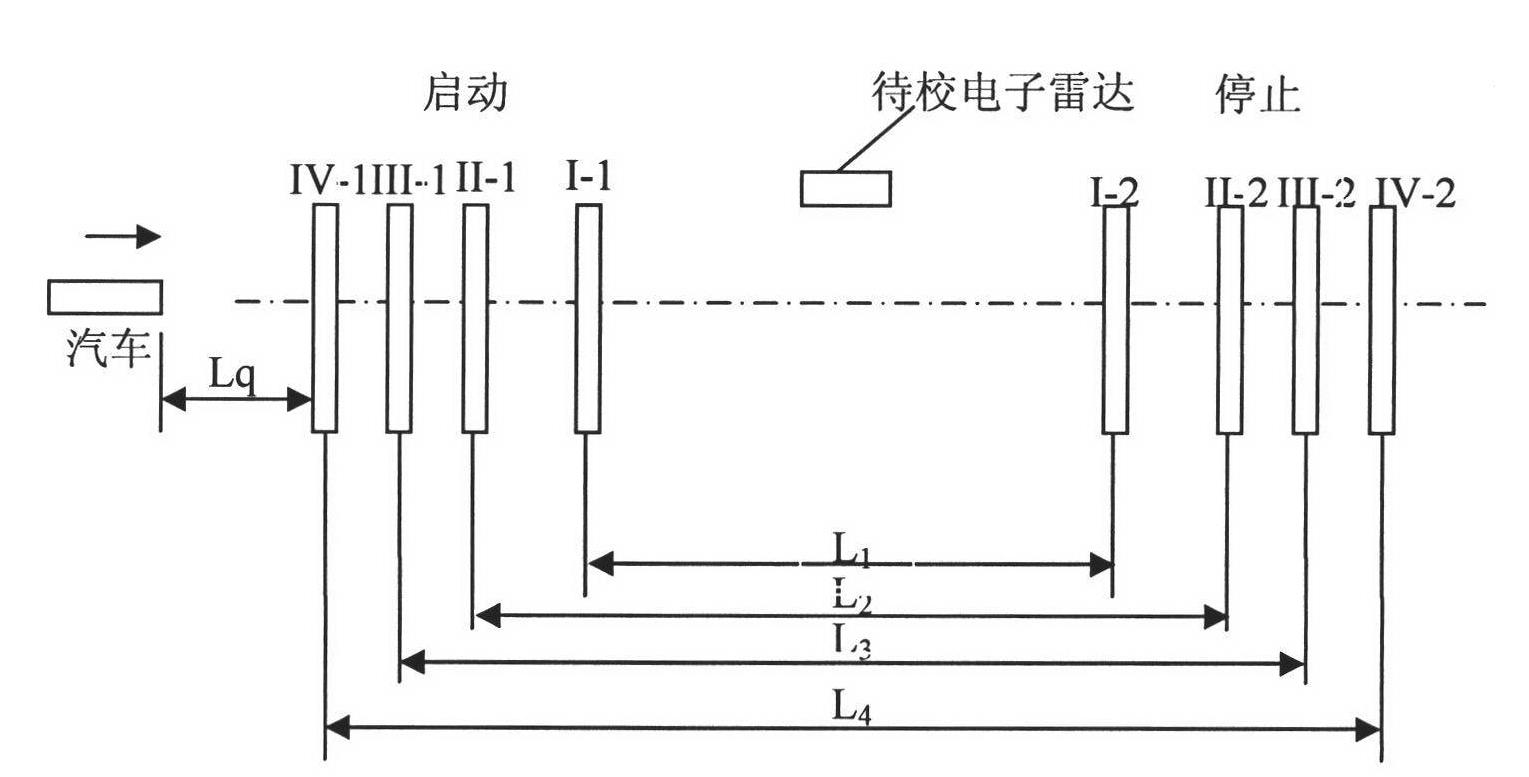
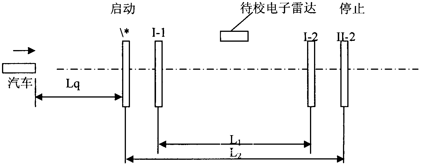
[0061] 4 pairs of standard speed measurement area interception devices (referred to as standard light curtain target) and a calibrated electronic radar dynamic speed measurement system device according to figure 2 As shown, the symmetrical arrangement is carried out, assuming that the distance between the two targets of the block device I is L1, the distance between the two targets of the block device II is L2, the distance between the two targets of the block device III is L3, and the distance between the two targets of the block device IV is L4 , the school electronic radar speed measurement system device is placed in the block device, the distance between the car and the first target is Lq, and according to the principle of average speed measurement, the measured value of the moving speed of the car measured by each block device is v i : Among them, l1=50m, l2=65m, l3=75m, l4=85m, Lq=100m. The test site uses a horizontal straight lane. The car starts from the starting poin...
PUM
 Abstract
Description
Claims
Application Information
 - R&D
- Intellectual Property
- Life Sciences
- Materials
- Tech Scout
- Unparalleled Data Quality
- Higher Quality Content
- 60% Fewer Hallucinations
Browse by: Latest US Patents, China's latest patents, Technical Efficacy Thesaurus, Application Domain, Technology Topic, Popular Technical Reports.
© 2025 PatSnap. All rights reserved.Legal|Privacy policy|Modern Slavery Act Transparency Statement|Sitemap|About US| Contact US: help@patsnap.com


