
Programming or erasing method and device for resistive random access memory

A technology of resistive memory and programming method, applied in the field of microelectronics, can solve the problems of unreachable, discrete distribution, unstable programming voltage, etc., and achieve the effects of simple technical solution, improved discrete distribution, and prolonged service life

Active Publication Date: 2015-02-04
INST OF MICROELECTRONICS CHINESE ACAD OF SCI
View PDF3 Cites 0 Cited by
  • Summary
  • Abstract
  • Description
  • Claims
  • Application Information

AI Technical Summary

Problems solved by technology

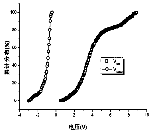
[0005] Due to the programming voltage (V Set ) and erase voltage (V Reset ) is very unstable and has a very discrete distribution, such as figure 1 As shown, in the above-mentioned operation method of programming and erasing of conventional resistive memory cells, the selection of pulse height during programming and erasing will be a very difficult thing
If the voltage pulse height is too small, the V of some memory cells cannot be reached. Set (or V Reset ) voltage, the resistance will not change from high (low) resistance state to low (high) resistance state, and the programming (or erasing) operation will fail; when the voltage pulse height is selected too large, it will increase the peripheral The manufacturing cost of the circuit, and especially in the process of RESET, it will also cause competition between RESET and the SET process-after RESET, the device returns from the high-resistance state SET to the low-resistance state, resulting in the instability of the resistive memory unit
These are very detrimental to memory program and erase operations

Method used

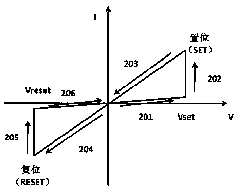
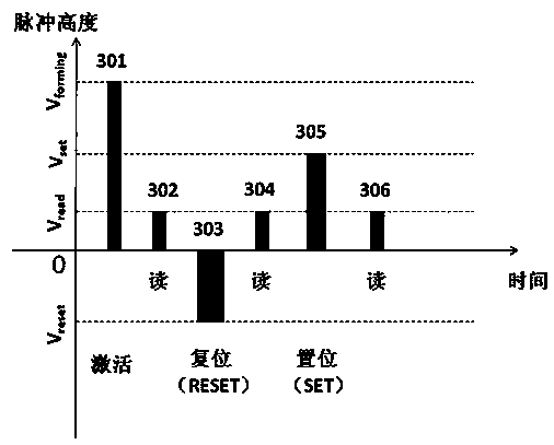

Image

  • Programming or erasing method and device for resistive random access memory
  • Programming or erasing method and device for resistive random access memory
  • Programming or erasing method and device for resistive random access memory

Examples


Embodiment Construction

[0037] In order to make the object, technical solution and advantages of the present invention clearer, the present invention will be described in further detail below in conjunction with specific embodiments and with reference to the accompanying drawings.

[0038] The invention provides an operation method for programming and erasing a resistive memory unit. By applying a stepped voltage pulse on the resistive memory unit and monitoring the current on the resistive memory unit in real time to observe the transition state of its resistance, Thus, the programming and erasing operations of the resistive switching unit are completed. This method can significantly improve the discrete distribution of the resistive parameter of the resistive memory unit.

[0039] like Figure 5 As shown, the present invention provides a schematic diagram of a programming and erasing device for a single RRAM cell. The resistor 503 is connected to the upper electrode of the RRAM unit 502, and the ...


PUM


Abstract

The invention discloses a programming or erasing method and a programming or erasing device for a resistive random access memory (RRAM). The device comprises a resistive random access memory unit (502) and a transistor (501), a series resistor (503), a signal generator, a current detection device and a control device, wherein the series resistor (503) is connected with the resistive random access memory unit in series, the signal generator is used for inputting continuous stepped impulse voltage signals to the resistive random access memory unit (502), the current detection device is used for detecting current on the series resistor (503), and the control device is used for judging whether a detection value of the current on the series resistor (503) is matched with a pre-set condition. When the detection value is matched with the pre-set condition, the control device controls the signal generator so as to stop signal output, and the programming or erasing operation of the resistive random access memory unit is finished. The method and the device can obviously improve discrete distribution of resistive parameters of the resistive random access memory unit, and can improve durability and prolong service life of devices.

Description

technical field [0001] The invention relates to the field of microelectronics, in particular to a method and device for programming or erasing a resistive variable memory unit. Background technique [0002] With the rapid development of modern information technology, the traditional Flash memory can no longer meet people's demand for large-capacity, low-power storage. Resistive RAM (RRAM), which has attracted extensive attention due to its simple structure, low power consumption, high density, fast operation speed, compatibility with CMOS process, and easy 3D integration, is one of the most promising next-generation non-volatile memories. one. despite this, figure 1 The resistive parameter of the shown resistive memory cell (such as V Set , V Reset The discrete distribution of voltage) is a bottleneck for its practical application. In order to improve the discrete distribution of the resistive switching parameters of the resistive variable memory cell, various solutions...

Claims


Application Information

Patent Timeline
Patent Type & Authority Patents(China)
IPC IPC(8): G11C11/56G11C16/14
Inventor 刘明王明吕杭炳刘琦龙世兵
Owner INST OF MICROELECTRONICS CHINESE ACAD OF SCI
Learn More