Variable inductor

An inductor and variable technology, applied in the direction of continuously variable inductors/transformers, printed inductors, transformer/inductor components, etc. The problems of long path and small Q value can achieve the effect of facilitating large-scale industrial production, low processing cost and high working frequency.

Inactive Publication Date: 2012-07-25
YANTEL CORP
View PDF9 Cites 2 Cited by
  • Summary
  • Abstract
  • Description
  • Claims
  • Application Information

AI Technical Summary

Problems solved by technology

However, when the frequency of use is higher, such as above several thousand MHz, the existing centralized parameter adjustable inductors can no longer reflect the characteristics of the inductor, the frequency characteristics deteriorate, the Q value becomes smaller, and the efficiency of the inductor has been lost.
[0003] Therefore, the applicant submitted a patent application for an adjustable inductor on May 10, 2004, the authorization number: ZL 200410027166.9, but it is difficult to achieve a higher Q value for the adjustable inductor; Submitted a patent application for a segmented adjustable inductor on May 12, the authorization number: ZL200610156510.3, but the segmented adjustable inductor has a large volume and a long path for the RF signal to pass, which will increase unnecessary signal insertion loss
The applicant submitted a patent application for an electric parameter adjustment system and device on July 28, 2008, application number: 200810144258.3. Although the electric adjustment device overcomes the previous weakness, its inductance cannot be continuously changed
[0004] In addition, the inductance of the existing adjustable inductor is made of copper enameled wi

Method used


Image

  • Variable inductor
  • Variable inductor
  • Variable inductor

Examples


Embodiment Construction

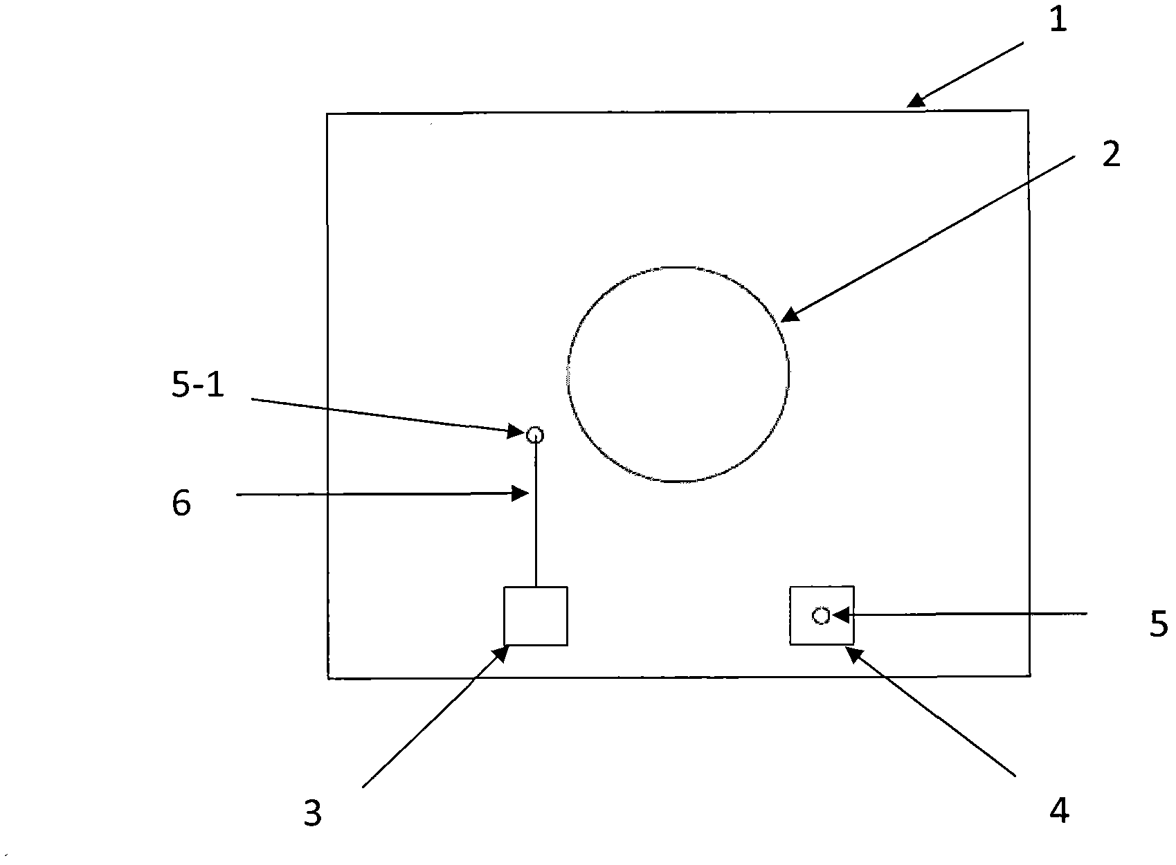
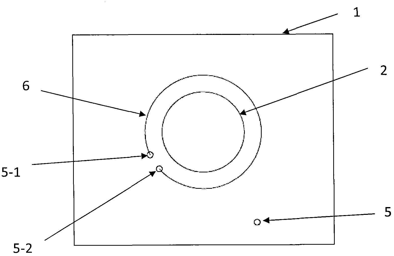
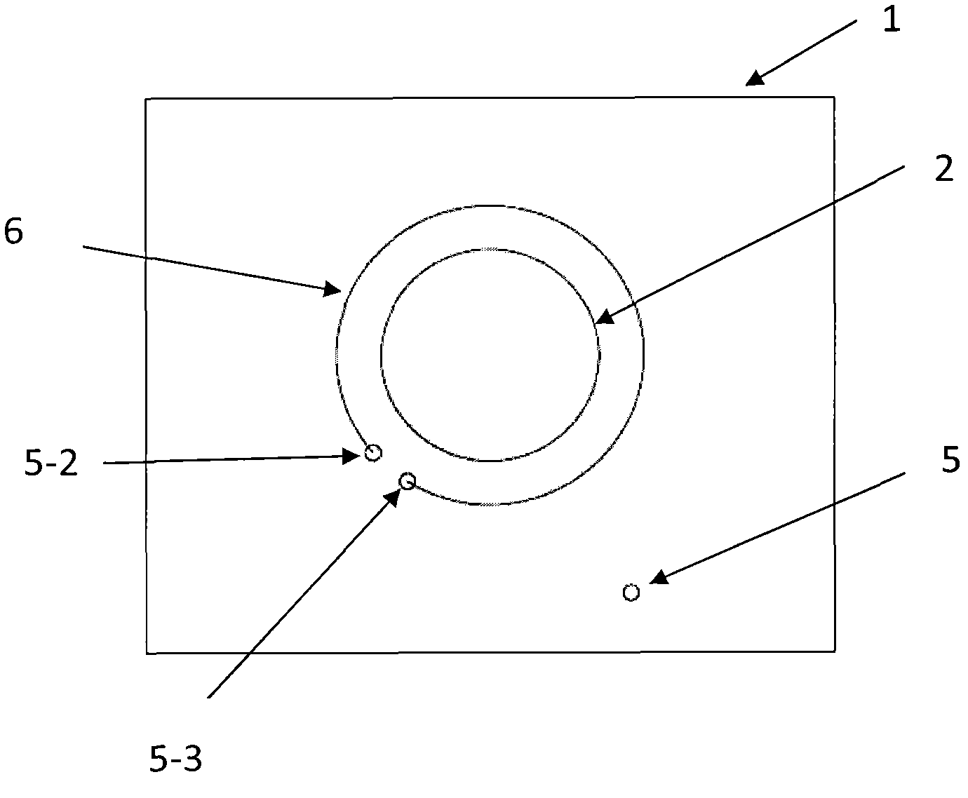
[0029] The variable inductor of the first embodiment of the present invention includes a substrate 1, an inductor 6 printed on the substrate, a pair of electrodes 3, 4, and a core 7 of the inductor 6. The substrate can be a one-layer or multi-layer PCB. The PCB in this embodiment is a 9-layer PCB board. The inductor 6 is a metal microstrip line (referred to as a metal wire) printed (or called printed) on the 9-layer PCB. Its shape is a coil. The width of the microstrip line made can determine the power and inductance of the inductor 6. There is a hole on the substrate 1. In this embodiment, a hole 2 is opened in the center of the substrate 1. The hole 2 can be a hole of other shapes such as a round hole, a square hole, or a triangular hole. This embodiment is a round hole, which is easy to process. The radius of the circular hole is smaller than the radius of the inductor 6 coil. The core 7 is also a cylinder. The core 7 can also be a square cylinder, a triangular cylinder, ...


PUM


Abstract

The invention discloses a variable inductor, which comprises a substrate, a core, an inductor body and a pair of electrodes of the inductor body, wherein the inductor body is printed on the substrate, the substrate is provided with a hole, and the core is inserted into the hole and moves along the length direction of the hole. Continuous variability of inductance of high-frequency microwave is realized by changing position of the core.

Description

Technical field [0001] The invention relates to a variable inductor, in particular to a variable inductor that can be used in various high-frequency and microwave circuits. Background technique [0002] In the electronic device family, the existence of adjustable inductors makes the production of electronic circuits more flexible and convenient. In electronic circuits below several hundred MHz, tunable inductors have been widely used, such as matching circuits and tuning circuits. However, when the operating frequency is higher, such as above several thousand MHz, the existing lumped parameter adjustable inductors can no longer reflect the characteristics of the inductance, the frequency characteristics become worse, the Q value becomes smaller, and the efficiency of the use of the inductor is lost. [0003] Therefore, the applicant submitted a patent application for a tunable inductor on May 10, 2004, with the authorization number: ZL 200410027166.9, but it is difficult for the t...

Claims


Application Information

Patent Timeline
IPC IPC(8): H01F21/02H01F21/06
CPCH01F21/02H01F27/2804H01F21/06H01F2017/006
Inventor 阎跃军
Owner YANTEL CORP
Why Eureka
Try Eureka