Millimeter wave waveguide communication system

A communication system, millimeter wave technology, applied in ultrasonic/sonic/infrasonic transmission systems, waveguides, transmission systems, etc., can solve problems such as affecting data bandwidth, millimeter wave leakage, reducing the number of waveguides, etc., to meet the requirements of high density and high speed. interconnect requirements, high data transfer rates, and improved signal quality

Active Publication Date: 2012-07-25
NAT CENT FOR ADVANCED PACKAGING
View PDF4 Cites 13 Cited by
  • Summary
  • Abstract
  • Description
  • Claims
  • Application Information

AI Technical Summary

Problems solved by technology

[0006] However, the applicant realized that the above-mentioned millimeter-wave communication system has the following technical defects: (1) There is a phenomenon of millimeter-wave leakage on the outer surface of the plastic waveguide, which leads to an electric field leaking around the plastic waveguide, extending about one wavelength. In order to reduce For the coupling of the leakage electric field, there must be a sufficient distance between the waveguides, which indirectly increases the size of the waveguide and reduces the number of waveguides; (2) At both ends of the waveguide, there is a phenomenon of millimeter wave reflection, which leads to the transmission The quality of the signal is reduced; (3) The refractive index of the plastic waveguide is low, which...

Method used


Image

  • Millimeter wave waveguide communication system
  • Millimeter wave waveguide communication system
  • Millimeter wave waveguide communication system

Examples


Embodiment Construction

[0050] In order to make the object, technical solution and advantages of the present invention clearer, the present invention will be described in further detail below in conjunction with specific embodiments and with reference to the accompanying drawings. It should be noted that while examples of parameters including particular values ​​may be provided herein, it should be understood that the parameters need not be exactly equal to the corresponding values, but rather may approximate the values ​​within acceptable error margins or design constraints.

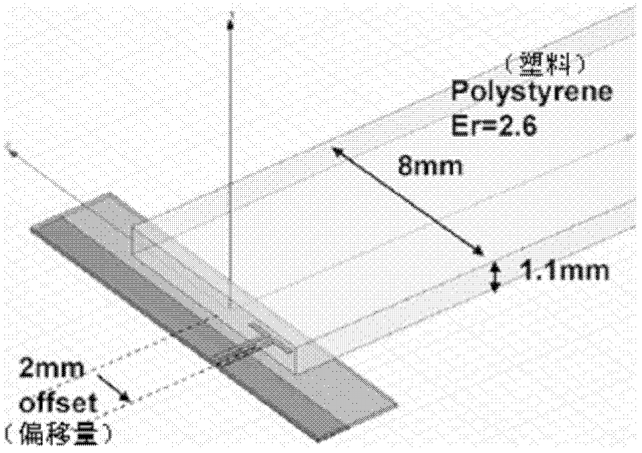
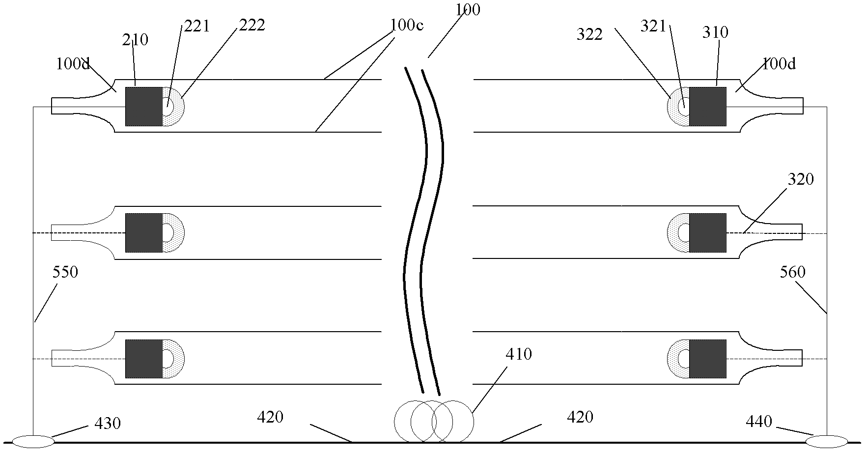
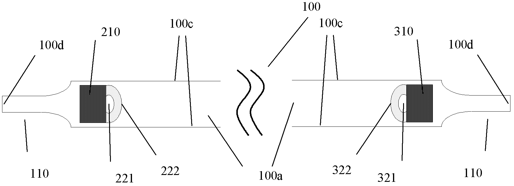
[0051]In the millimeter wave waveguide communication system of the present invention, a conductive wall to prevent millimeter wave leakage is designed on the surface of the waveguide to reduce the coupling of the leakage electric field; a structure to prevent millimeter wave reflection is designed on the end face of the waveguide to improve signal transmission quality; silicon material is used The waveguide improves the integra...


PUM

PropertyMeasurementUnit
Widthaaaaaaaaaa

Abstract

The invention provides a millimeter wave waveguide communication system. The millimeter wave waveguide communication system comprises a clock module and at least two groups of millimeter wave receiving/sending channels, wherein the clock module is used for respectively providing clock signals for the sending ends and receiving ends of the at least two groups of millimeter wave receiving/sending channels; each group of the millimeter wave receiving/sending channels comprises an emitter module, a receiving end module and a transmission waveguide, wherein the transmission waveguide is positioned between the emitter module and the receiver module and is used for providing a transmission channel for the millimeter wave; the areas on the top, side and/or bottom of the transmission waveguide, except part of areas on which active devices and accessories are arranged on, are plated with metal conductive walls to form electromagnetic shielding of the transmission waveguide in the adjacent millimeter wave receiving/sending channels. The metal conductive wall of the layer can minimize the crosstalk between the channels during high-speed communication, and therefore, data bandwidth and data throughput of the millimeter wave communication system are improved.

Description

technical field [0001] The present invention relates to the technical field of millimeter wave communication in the information electronics industry, and in particular to a millimeter wave waveguide communication system for data transmission between two points through a millimeter wave waveguide. The millimeter wave waveguide communication system can be used as a high-speed data link between a processor and a memory. transfer bus. Background technique [0002] Traditional computer hardware is based in part on three ubiquitous and well-established technologies: silicon, used to form transistors for logic operations, memory, and signal amplifiers; composite materials, used for isolation for discrete component integration; and copper, used for data transmission. The emergence of multi-core processors, the parallel and simultaneous execution of instructions, and the development of optimized software have continuously improved the performance of computers and put forward higher r...

Claims


Application Information

Patent Timeline
IPC IPC(8): H01P3/10H04B11/00
Inventor 吉多蒂·丹尼尔王启东林福江朱光
Owner NAT CENT FOR ADVANCED PACKAGING
Why Eureka
Try Eureka