Auto-cascade jet type refrigerator

A technology of ejector and refrigerator, which is applied in the direction of refrigerator, refrigeration components, refrigeration and liquefaction, etc., can solve the problems of high operating cost and complex structure, and achieve the effect of improving refrigeration performance, reducing compression ratio, and improving ejector efficiency

Inactive Publication Date: 2012-08-01
NINGBO INST OF TECH ZHEJIANG UNIV ZHEJIANG
View PDF8 Cites 33 Cited by
  • Summary
  • Abstract
  • Description
  • Claims
  • Application Information

AI Technical Summary

Problems solved by technology

However, the above-mentioned refrigeration system uses a rectification tower a

Method used


Image

  • Auto-cascade jet type refrigerator
  • Auto-cascade jet type refrigerator
  • Auto-cascade jet type refrigerator

Examples


Embodiment 2

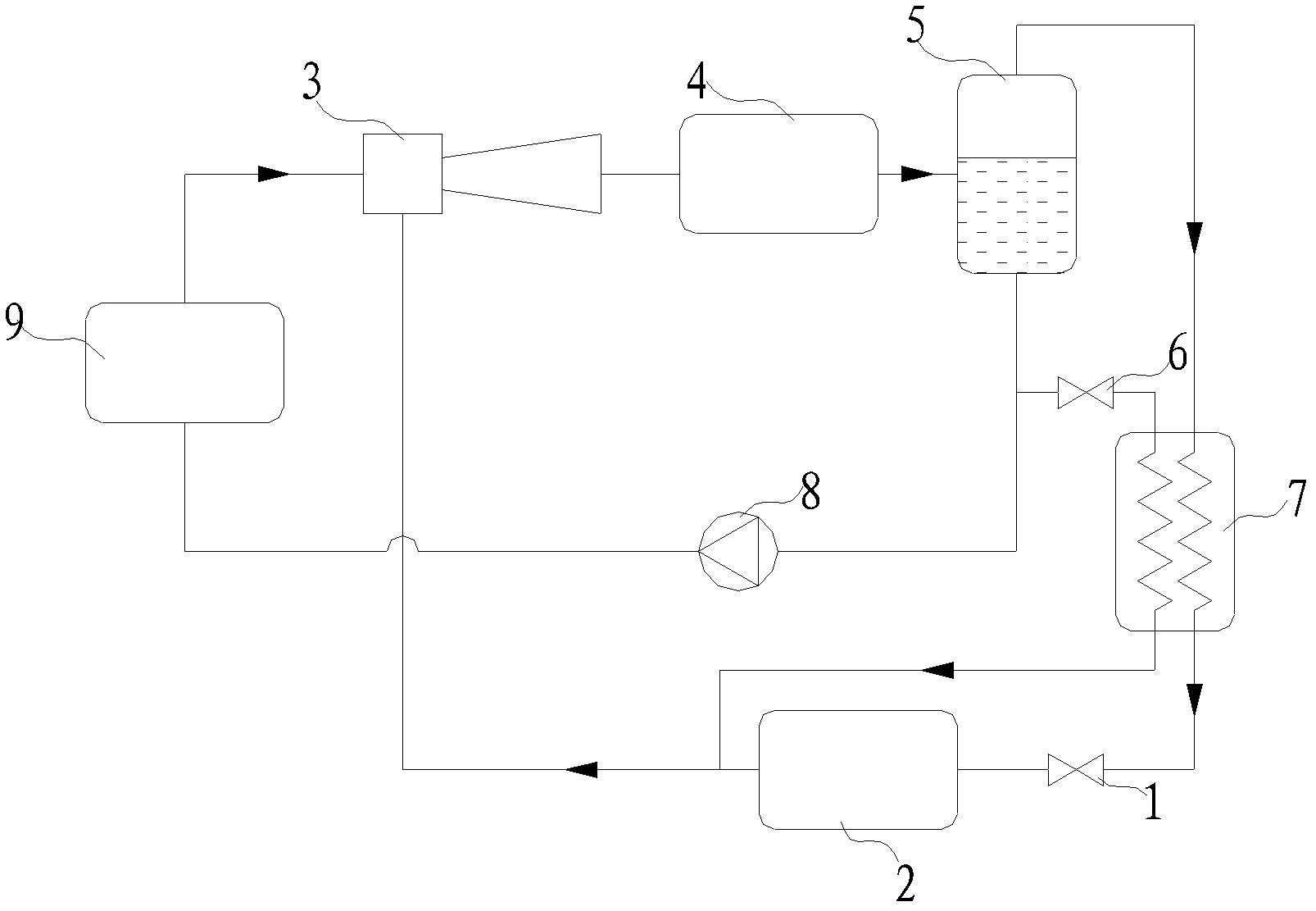
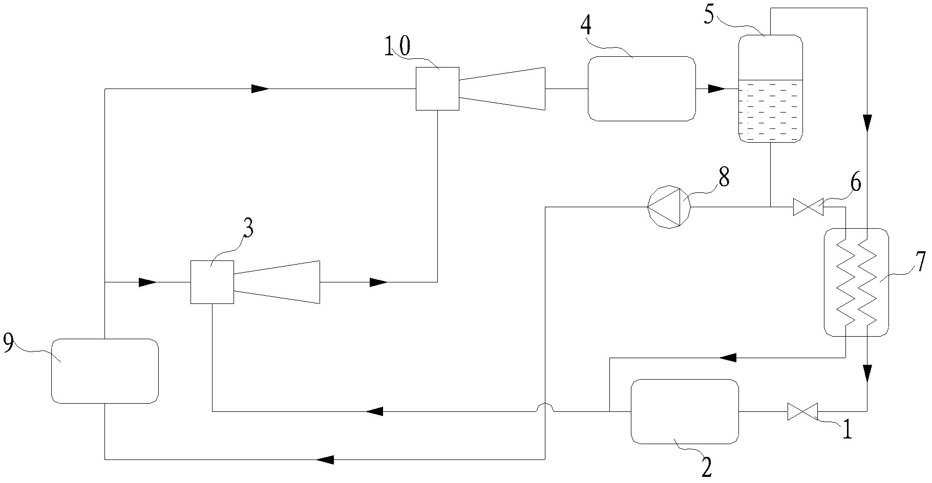
[0033] This embodiment is an improvement carried out on the basis of Example 1, as figure 2 shown in figure 1 On the basis of the system shown, the first ejector 3 and the second ejector 10 are connected in series and then connected to the condenser 4 . There is a pipeline communicating between the outlet of the first generator 9 and the inlet of the working fluid of the second injector 10 .

[0034] The specific connection is: a second injector 10 is provided on the pipeline between the first injector 3 and the first condenser 4; the working fluid inlet of the second injector 10 communicates with the working fluid outlet of the first generator 9, and the second injector 10 communicates with the working medium outlet of the first generator 9, The injection fluid inlet of the second injector 10 communicates with the injection outlet of the first injector 3 , and the injection outlet of the second injector 10 communicates with the working medium inlet of the first condenser 4 ...

Embodiment 3

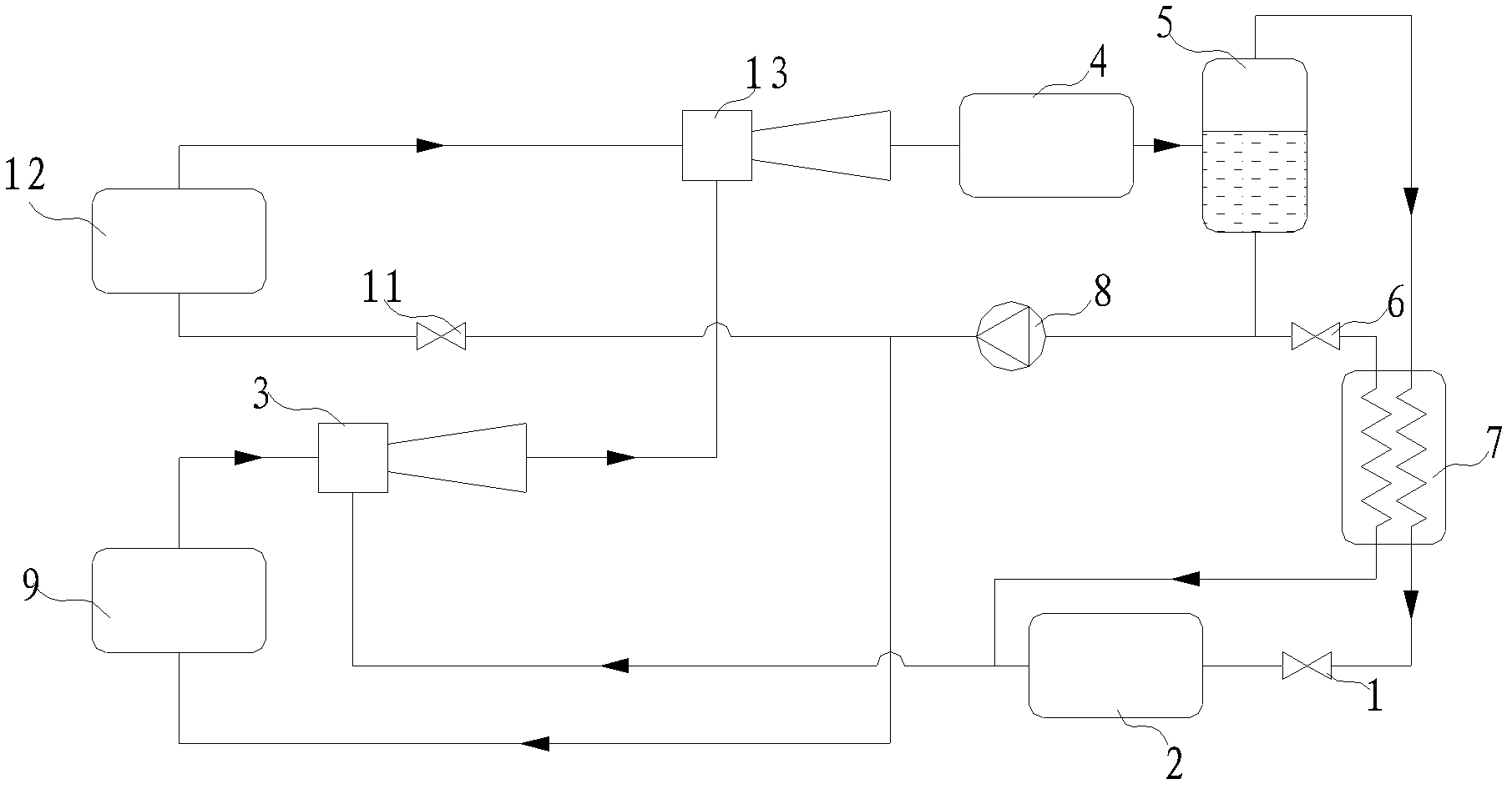
[0037] Such as image 3 As shown, this implementation is an improvement on the basis of Example 1. The third throttling element 11 and the second generator 12 are connected in series between the outlet of the first circulation pump 8 and the inlet of the working fluid of the third injector 13 .

[0038] The specific connections are: the working fluid inlet of the third injector 13 communicates with the working medium outlet of the second generator 12, the injection fluid inlet of the third injector 13 communicates with the injection outlet of the first injector 3, and the third injector The injection outlet of 13 communicates with the working medium inlet of the first condenser 4; the third throttling element 11 is arranged on the pipeline between the working medium outlet of the first circulating pump 8 and the working medium inlet of the second generator 12. All the other parts are connected with the embodiment 1.

[0039] Compared with Example 1, the working fluid flow in ...

Embodiment 4

[0041] Such as Figure 4 As shown, this embodiment is an improvement on the basis of Embodiment 4, wherein the third throttling element 11 is located on the pipeline between the first generator 9 .

[0042] The specific connection is: the working medium inlet of the second generator 12 communicates with the working medium outlet of the first circulation pump 8 . The working fluid outlet of the third throttling element 11 is connected with the working fluid inlet of the first generator 9 , and the working fluid inlet of the third throttling element 11 is connected with the working fluid outlet of the first circulating pump 8 . All the other parts are connected with the embodiment 1. All the other parts are connected with embodiment 3.

[0043] Compared with Example 4, the difference in working fluid flow in this example is that part of the liquid at the outlet of the first circulating pump 8 directly enters the second generator 12, and becomes a high-pressure gas after being ...


PUM


Abstract

The invention discloses an auto-cascade jet type refrigerator, which comprises a first throttling element, an evaporator, a first jet, a first condenser, a first circulating pump, a first generator, a first gas-liquid separator, a second throttling element and an evaporator condenser; the first jet is sequentially connected in series with the first condenser, the first gas-liquid separator, the first circulating pump and the first generator to form a loop; the evaporator condenser, the first throttling element and the evaporator are sequentially connected in series between the gas phase outlet of the first gas-liquid separator and the first jet; and the second throttling element and the evaporator condenser are sequentially connected in series between the liquid phase outlet of the first gas-liquid separator and the first jet. The invention breaks through the constraint of the traditional idea, and adopts the method of auto-cascade to decrease the compression ratio to be reached by a refrigeration system in order to solve the problem that the jet coefficient is abruptly decreased after the difference between the backpressure and jet pressure of the jet exceeds a certain value, and the auto-cascade jet type refrigerator can utilize the jet type refrigeration technology to achieve low refrigeration temperature.

Description

technical field [0001] The invention belongs to the technical field of refrigeration, in particular to a self-cascading jet refrigerator. Background technique [0002] Ejection refrigeration technology is a heat-driven refrigeration technology. Compared with mechanical compression refrigeration technology, its main advantage is that it only consumes little mechanical energy and can directly use heat energy as the driving energy. It has the advantages of simple structure, small size and low cost. Low cost, reliable operation, long service life and other advantages. Jet refrigeration is a refrigeration method driven by low-grade energy, which can effectively utilize renewable energy such as solar energy and geothermal energy, as well as industrial waste heat and waste heat; the refrigerant used in jet refrigeration is mainly water, hydrocarbons or hydrofluorine Hydrocarbon refrigerants can avoid the use of CFCs or HCFCs refrigerants that destroy the ozone layer. [0003] Due...

Claims


Application Information

Patent Timeline
IPC IPC(8): F25B9/08F25B41/06
Inventor 陈光明陈少杰杨申音李建新王永川郑皎徐飞
Owner NINGBO INST OF TECH ZHEJIANG UNIV ZHEJIANG
Why Eureka
Try Eureka