Air conditioner heat pump unit with antifreeze solution regenerated heat recovery device

A heat recovery device and antifreeze solution technology, applied in heat recovery systems, refrigerators, refrigeration components, etc., can solve problems such as limited application areas, large solution storage space, and freezing of refrigerants to avoid frosting or The effect of freezing, increasing the concentration of the solution, and increasing the evaporation temperature

Active Publication Date: 2014-02-12
GUANGZHOU WIDE IND
View PDF8 Cites 0 Cited by
  • Summary
  • Abstract
  • Description
  • Claims
  • Application Information

AI Technical Summary

Problems solved by technology

However, in the currently commonly used air-conditioning heat pump units, when the temperature of the brine (cooling water) in the evaporative condenser is lower than 0°C, the brine will freeze into ice, and the evaporative condenser and its connected parts may There is a danger of being damaged by expansion cracks. At this time, if an antifreeze solution with a suitable concentration can be obtained, it can ensure that all parts work normally at low temperatures.
In addition, when the heat pump works, after the evaporative condenser takes heat from the air, the temperature of the air will drop, which will cause the moisture in the air to condense, and this part of the condensed water will enter the antifreeze solution, which will lead to the dilution of the antifreeze solution. As the concentration of the solution decreases, the freezing point of the antifreeze solution will increase. If the concentration of the antifreeze solution (or solution regeneration) is not increased in time, the solution pool, water pump and other components of the evaporative condenser still have the risk of expansion and cracking
In order to solve this problem, at present, the diluted solution is often added with high-concentration antifreeze, and the overflowed diluted antifreeze solution is stored in an indoor or underground solution storage tank. After the outdoor temperature rises, the diluted antifreeze The solution is pumped into the evaporative condenser, and the energy in the air is used to realize the regeneration of the solution. This method inevitably requires a high concentration of antifreeze, a large-capacity storage tank for concentrated solution and dilute solution, resulting in a large amount of antifreeze and a large solution storage space. Huge, extremely high initial investment and increased operating costs of antifreeze greatly limit the applicable area of ​​evaporative condenser as a heat pump heat extraction device in low temperature areas

Method used


Image

  • Air conditioner heat pump unit with antifreeze solution regenerated heat recovery device
  • Air conditioner heat pump unit with antifreeze solution regenerated heat recovery device
  • Air conditioner heat pump unit with antifreeze solution regenerated heat recovery device

Examples


Embodiment 1

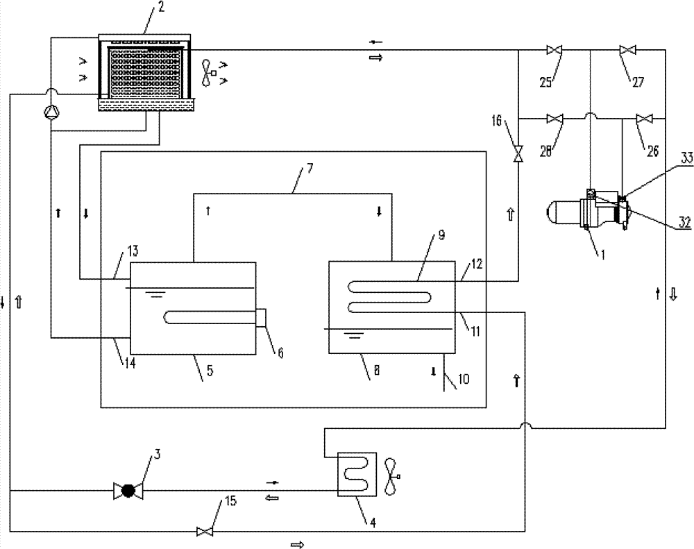
[0034] In this embodiment, an air-conditioning heat pump unit with an antifreeze solution regenerative heat recovery device, such as figure 1 As shown, it includes a compressor 1, an evaporative condenser 2, at least one throttling device 3, at least one evaporator 4 and an antifreeze solution regeneration heat recovery device, and the interface at one end of the compressor 1 is respectively connected to the gas pipe of the evaporative condenser 2 and the gas pipe of the evaporator 4, the interface at the other end of the compressor 1 is respectively connected to the gas pipe of the evaporative condenser 2 and the gas pipe of the evaporator 4, and the connecting pipe where the throttling device 3 is located is respectively connected to the liquid pipe of the evaporator 4 and the liquid pipe of the evaporative condenser 2; the cooling water system of the evaporative condenser 2 is equipped with an antifreeze solution regeneration heat recovery device;

[0035] The antifreeze so...

Embodiment 2

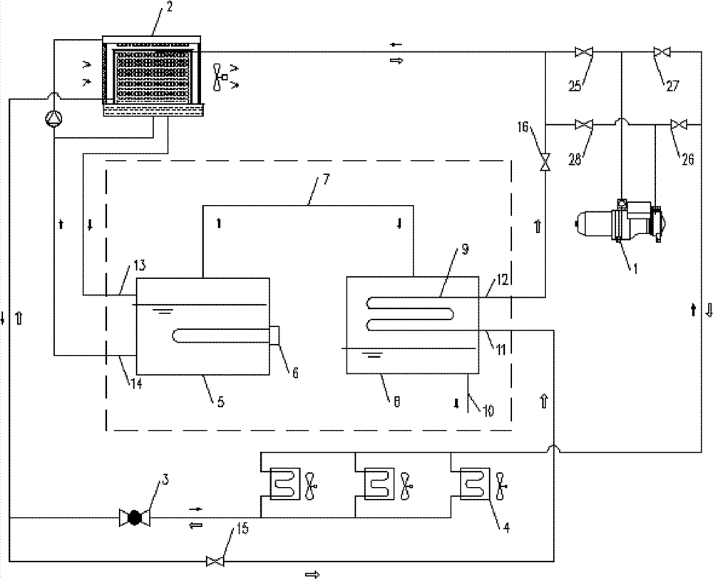
[0039] In this embodiment, an air-conditioning heat pump unit with an antifreeze solution regenerative heat recovery device, such as figure 2 As shown, compared with Example 1, the difference is that a plurality of evaporators 4 are arranged in parallel. After a plurality of evaporators are connected in parallel, one end of the evaporator group is connected to the compressor 1, and the other end of the evaporator group is connected to the compressor 1. One end is connected with the throttling device 3 .

Embodiment 3

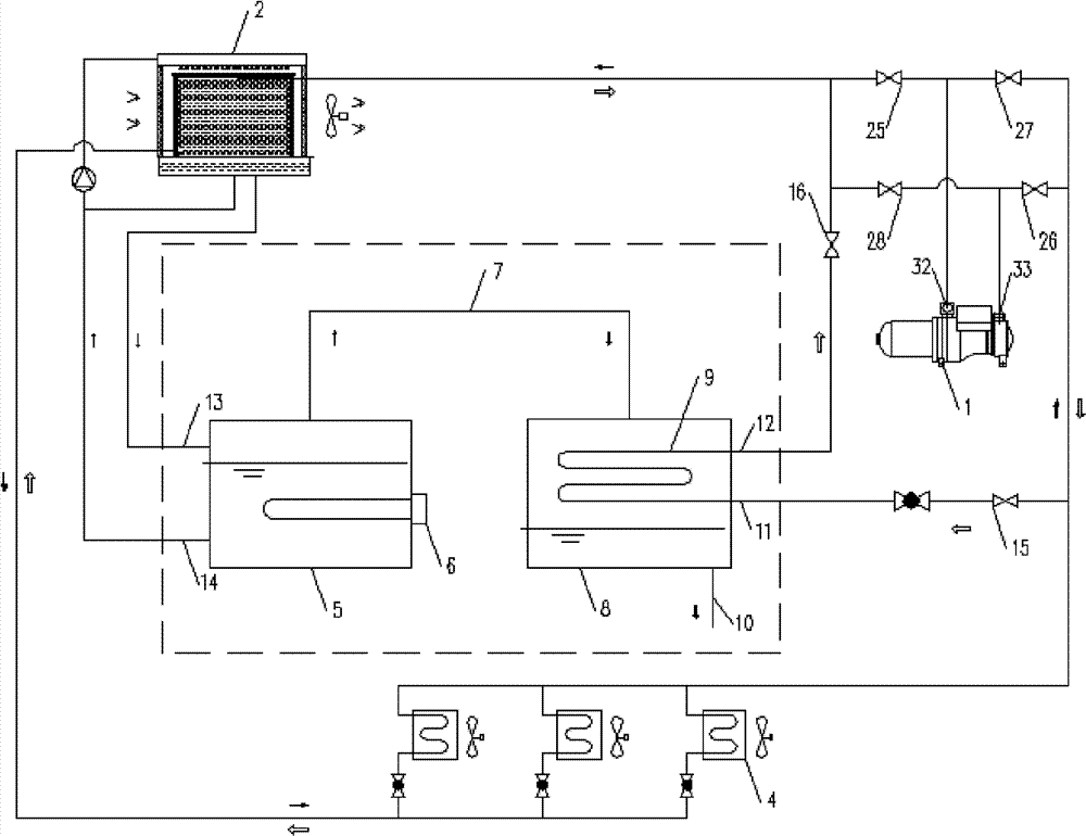
[0041] In this embodiment, an air-conditioning heat pump unit with an antifreeze solution regenerative heat recovery device, such as image 3 As shown, compared with Embodiment 1, the difference is that a plurality of throttling devices 3 are provided, so that the flow of refrigerant entering the first heat exchanger 9 and the evaporator 4 can be accurately controlled.


PUM


Abstract

The invention discloses an air conditioner heat pump unit with an antifreeze solution regenerated heat recovery device. The air conditioner heat pump unit comprises a compressor, an evaporative condenser, at least one throttling device, at least one evaporator and the antifreeze solution regenerated heat recovery device, wherein the interface of one end of the compressor is respectively connected with the gas tube of the evaporative condenser and the gas tube of the evaporator; the interface of the other end of the compressor is simultaneously respectively connected with the gas tube of the evaporative condenser and the gas tube of the evaporator, and the connecting pipeline of the throttling device is respectively connected with the liquid tube of the evaporator and the liquid tube of the evaporative condenser; and the cooling water system of the evaporative condenser is provided with the antifreeze solution regenerated heat recovery device. By using the antifreeze solution regenerated heat recovery device, the solution regeneration and recycle of a solution regeneration energy source are realized, and an antifreeze solution is avoided to be frozen; and technology security is provided for the air conditioner cold-hot water unit to take heat from outdoor air to realize high efficient, continuous and stable heat supply.

Description

technical field [0001] The invention relates to the technical field of heat pump units for air conditioners, in particular to an air conditioner heat pump unit with an antifreeze solution regeneration heat recovery device. Background technique [0002] The use of evaporative condensers to extract heat from the outdoor air and provide heat energy for heat pump air conditioners in winter is an important way to achieve efficient and stable heat supply. Compared with air source heat pumps, it has high heat exchange efficiency and saves heat exchanger materials. , can achieve continuous heating, and has a significant prospect of energy saving and emission reduction. However, in the currently commonly used air-conditioning heat pump units, when the temperature of the brine (cooling water) in the evaporative condenser is lower than 0°C, the brine will freeze into ice, and the evaporative condenser and its connected parts may There is a danger of being damaged by expansion cracks. ...

Claims


Application Information

Patent Timeline
Patent Type & Authority Patents(China)
IPC IPC(8): F25B41/00F25B41/06
CPCY02B30/52
Inventor 李志明石文星李先庭张勇王宝龙谭栋
Owner GUANGZHOU WIDE IND
Why Eureka
Try Eureka