Compact liquid crystal projection light engine system using mixed light source

A liquid crystal projection and mixed light source technology, which is applied in the field of projection display systems, can solve the problems of low output measurement, high cost, and reduced color purity, and achieve the effects of increased output brightness, security assurance, and weakened speckle

Active Publication Date: 2012-08-01
杭州研明光电技术有限公司
View PDF6 Cites 9 Cited by
  • Summary
  • Abstract
  • Description
  • Claims
  • Application Information

AI Technical Summary

Problems solved by technology

Although the LED stimulates the phosphor to significantly improve the brightness, there are also shortcomings: 1) The spectral range is too wide. Although the main wavelength is in the green light range, there is still some energy in other wavelength ranges.
2) The color purity is greatly reduced, and the energy in the range of other primary colors cannot be effectively utilized by the system
3) The luminous angle of the fluorescent powder excited LED increases, which increases the etendue of the light source, which brings pressure to the design of the subsequent system
However, laser projection also has disadvantages that are difficult to overcome: 1) true green laser has not yet been commercialized, and the cost is too high
If tri-color LED lighting is used, the output of the whole system is still low

Method used


Image

  • Compact liquid crystal projection light engine system using mixed light source
  • Compact liquid crystal projection light engine system using mixed light source
  • Compact liquid crystal projection light engine system using mixed light source

Examples


Embodiment 1

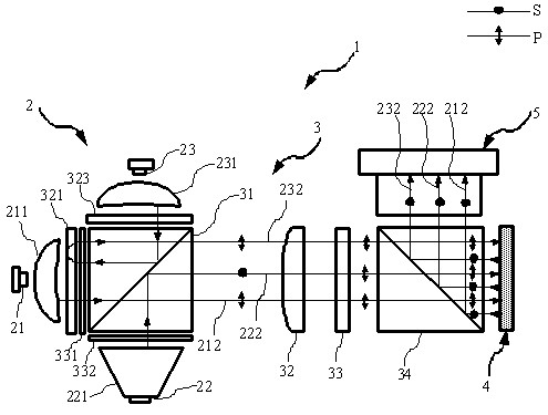
[0029] figure 1 The first embodiment of the reflective liquid crystal projection display system 1 using mixed light sources of the present invention is given, including a light source module 2 , a polarized light management module 3 , an image information module 4 and a projection lens 5 .

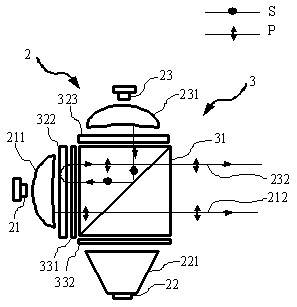
[0030] The light source module 2 includes a red laser 21, a blue laser 23, a green LED 22, a red laser beam expander and shaper 211, a blue laser beam expander and shaper 231, a green light homogenizer 221, a red laser 21 and a red laser beam expander and shaper 211 is adjacent, the blue laser 23 is adjacent to the blue laser beam expander and shaper 231 , and the green LED 22 is connected to the green homogenizer 221 .

[0031] The polarized light emitted by the red laser 21 and the blue laser 23 passes through the red laser beam expander and shaper 211 and the blue laser beam expander and shaper 231 respectively, and then becomes a rectangular beam required for illumination. The natural...

Embodiment 2

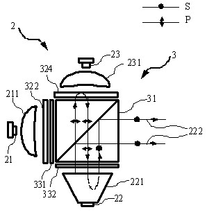
[0044] Figure 4 A second embodiment of the present invention is given. Compared with the first embodiment, the difference of this embodiment is that the light source module 2 consists of blue lasers 23 and 25, a blue beam expander and shaper 231, a transparent blue anti-green filter 324, a green fluorescent plate 325, a green Composed of beam expander and shaper 251, red LED 24 and red homogenizer 241, it provides mixed three-primary-color illumination for the system. The polarization color combining unit consists of a first PBS 31, a red-transmitting anti-blue filter 321, a wide-band quarter-wave plate 331, a second wide-band quarter-wave plate 332, and a blue-transmitting anti-red-green quarter The wave plate 323 is composed. Using the blue laser to excite the green phosphor to generate green light can increase the brightness of the green light with the largest proportion in the projection, which is conducive to improving the brightness of the whole machine.

[0045] The...

Embodiment 3

[0050] Figure 8 A third embodiment of the present invention is given. Compared with the second embodiment, this embodiment uses a red laser 21 and a red laser beam expander and shaper 211 to replace the red LED 24 and the red homogenizer 241 . Compared with Example 3, the brightness of red light in this example will be further improved, so that the brightness of the whole machine will be improved, but the speckle phenomenon caused by the increase of laser components will be more obvious. In this embodiment, since the blue light part and the green light part remain unchanged, the ray trajectories and polarization states of the blue light 232 and the green light 222 are as follows: Figure 6 and Figure 7 shown.

[0051] Figure 9 The traveling route of the red light beam 212 in the third embodiment is given. The light emitted from the red laser 21 passes through the red laser beam expander and shaper 211 , passes through the red and anti-blue filter 321 and the broadband ...


PUM


Abstract

The invention provides a compact liquid crystal projection light engine system using a mixed light source. The light engine system comprises a light source module, a polarized light management module, an image signal module and a projection lens. The light source module comprises a high-brightness laser, a noncoherent LED (Light Emitting Diode), a fluorescent device and the like; the output brightness of the projection system is largely increased and safety, environment friendliness, colorful projected image and high-definition image quality are obtained. The polarized light management module comprises a polarization beam splitter (PBS), a polarization color combining device and the like; three-primary-color mixed lights in different polarization states are integrated into the same polarized light and radiate to the image signal module; the image signal module is a single reflective liquid crystal light modulating device and is used for loading the image signals to the three-primary-color polarized light in sequence according to the image signal corresponding to each primary color; and a projection lens is used for projecting the light carrying the image signal to a screen.

Description

technical field [0001] The invention relates to a projection display system, in particular to a compact reflective liquid crystal projection light engine system using a mixed three primary color light source. Background technique [0002] Projection display has become the mainstream method of large-screen high-definition dynamic display, and is widely used in important links such as business, education, scientific research, entertainment and family. In recent years, with the rapid development of many technologies such as microelectronics, optics, and processing technology, as well as the popularization of modern business mobile office models and the increase of handheld digital products, miniaturization has become a new direction for the development of projection display technology. Micro-projectors have significant advantages such as lightness and ease of use, and can be combined with various consumer electronics products, which makes the application of micro-projectors inf...

Claims


Application Information

Patent Timeline
Patent Type & Authority Applications(China)
IPC IPC(8): G03B21/20G02B27/28G02B27/18G02B27/09G02B27/48F21V13/00F21Y101/02F21Y115/10
Inventor 贺银波陆巍
Owner 杭州研明光电技术有限公司
Why Eureka
Try Eureka