Compound lime kiln

A lime kiln and composite technology, which is applied in the field of chemical production equipment and building materials, can solve the problems of affecting the combustion of the calcination zone, affecting the calcination effect, and increasing the pressure load of the kiln body, so as to improve the calcination effect, effectively use energy, and reduce pressure. load effect

Active Publication Date: 2012-08-08
SHIJIAZHUANG XINHUA IND FURNACE CO LTD
View PDF6 Cites 11 Cited by
  • Summary
  • Abstract
  • Description
  • Claims
  • Application Information

AI Technical Summary

Problems solved by technology

The disadvantage of this process is that the direction of the furnace gas flow in the shaft kiln is opposite to that of the stone material, that is, the stone material moves from top to bottom, and the furnace gas flows from bottom to top. Gas segregation phenomenon causes uneven heating of limestone and affects product quality
Large and small particles are mixed and calcined together, the small particles will fill the gaps between the large particles, and high gas resistance will be generated in the kiln body, which will affect the calcination effect and cause raw or over-fired
Therefore, generally calcined limestone chooses stones with a particle size of 30-100 mm, and stones with a particle size of less than 30 mm can only be discarded or used for other purposes, which is a waste of resources.
[0004] On the other hand, since the cooling air enters the kiln body from the bottom of the kiln body, passes through the cooling zone to cool the lime, then passes through the calcination zone and the preheating zone, and then flows from the upper part of the kiln together with the flue gas to the exhaust system. The cooling wind passes through the entire furnace, affecting the calcination zone. Combustion increases the pressure load in the kiln body

Method used


Image

  • Compound lime kiln
  • Compound lime kiln
  • Compound lime kiln

Examples


Embodiment 1

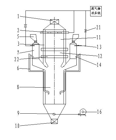
[0017] The composite lime kiln of the present invention is as follows figure 1 As shown, it is a beam-type lime kiln, including a kiln body 3, a feeding device, a discharging device, a control system, two small particle kiln bins 7, two air ducts 6 and an exhaust gas discharge system. The kiln body is provided with a preheating zone 11 , a calcining zone 12 and a cooling zone 8 . The preheating belt is provided with two suction beams 2, the suction beam is provided with 10 suction holes, the suction beam is connected with the exhaust gas discharge system, the cooling belt is provided with a cooling air outlet 9, and the cooling air inlet is connected to the cooling fan 16 through a pipeline connect. The calcination belt is provided with two layers of combustion beams 22, 3 combustion beams in the upper layer and 2 combustion beams in the lower layer. Each combustion beam is provided with 10 burners, and the burners are gas fuel burners. The small particle kiln warehouse is ...

Embodiment 2

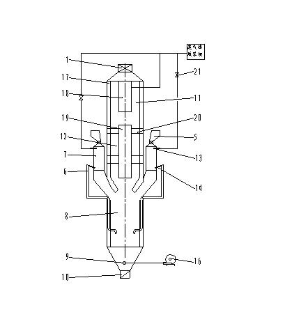
[0020] Another embodiment of the present invention is as figure 2 As shown, the lime kiln is a sleeve kiln, which is provided with a combustion chamber, an upper inner cylinder 18, a lower inner cylinder 19 and a fire bridge 20. The combustion chamber is divided into upper and lower layers, each layer is provided with 6 combustion chambers, the combustion chambers on the same layer are evenly arranged, the upper and lower combustion chambers are staggered, and each combustion chamber is connected with the inner cylinder through a fire bridge. The inner cylinder and the outer cylinder are arranged concentrically to form an annular space, and the limestone is preheated and calcined in the annular space. The fire bridge is an arch structure made of refractory bricks, and the high temperature flue gas generated by the combustion enters the limestone material layer through the space under the arch fire bridge. The limestone material enters the preheating zone of the kiln through ...

Embodiment 3

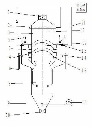
[0022] Another embodiment of the present invention is as follows image 3 As shown, the lime kiln is an arch bridge kiln, the calcination zone of the arch bridge kiln is provided with two layers of combustion arch bridges 4, the upper layer is provided with 4 combustion arch bridges, the lower layer is provided with 3 combustion arch bridges, and the two layers of combustion arch bridges are arranged in a staggered manner. The lower parts of the two ends of each combustion arch bridge are provided with burners 15. The burners are solid burners and gas burners. One burner can be used alone, or two burners can be used simultaneously. The preheating belt is provided with 3 suction beams 2 . Other structures and operation modes are the same as those in Embodiment 1.


PUM

PropertyMeasurementUnit
particle sizeaaaaaaaaaa
particle diameteraaaaaaaaaa

Abstract

The invention relates to a compound lime kiln, comprising a kiln body, a charging equipment, a discharging equipment, a control system and an exhaust system.A preheating zone, a\calcining zone and a cooling zone are in the kiln body. A smoke outlet or a fume extractor is arranged in the preheating zone, and the smoke outlet or the fume extractor is connected with the exhaust system. A cooling tuyere is arranged in the cooling zone, and a cooling air inlet is connected with a cooling fan. Two to four granule kiln bins are arranged in the device. Granule hoppers, granule charging locks and cooling air outlets are arranged in the granule kiln bins. The underpart of the granule kiln bins are connected with the cooling zone. The cooling air outlet is connected with the exhaust system. Granule kiln bins are arranged in the device in the invention, exhaust gas after lime cooling is utilized to preheat granule limestone materials, and simultaneously large particle and granule materials are calcined, so that the preheating fully utilizes resources of limestones, effectively utilizes energy, reduces consumption and improves productivity. The cooling air does not enter the calcining zone, which is beneficial to an improving of calcining effects of the calcining zone, a reducing of a pressure load of the kiln body and an improving of qualities of the lime products.

Description

technical field [0001] The invention belongs to the technical field of building materials and chemical production equipment, relates to equipment for calcining materials, and in particular relates to a composite lime kiln for simultaneously calcining large and small particles. Background technique [0002] Lime is an important building material as well as an important raw material in the fields of metallurgy and chemical industry. In the prior art, dolomite and limestone are used as raw materials, and a shaft kiln with a burning beam is used to calcine lime. The disadvantage of this process is that the direction of furnace gas flow in the shaft kiln is opposite to that of the stone material, that is, the stone material runs from top to bottom, the furnace gas flows from the bottom to the top, the gas resistance of the stone material is large, and the pressure in the furnace is high, which is easy to occur Gas segregation phenomenon, resulting in uneven heating of limestone, ...

Claims


Application Information

Patent Timeline
Patent Type & Authority Applications(China)
IPC IPC(8): C04B2/12
CPCY02P40/40
Inventor 贾会平
Owner SHIJIAZHUANG XINHUA IND FURNACE CO LTD
Why Eureka
Try Eureka