Method for producing laminated magnetic core

A magnetic core and metal surface technology, which is applied in the field of manufacturing laminated magnetic cores, can solve problems such as inability to handle, and achieve the effects of increasing power density, reducing eddy current loss, and reducing temperature

Inactive Publication Date: 2012-08-15
HEIDELBERGER DRUCKMASHINEN AG
View PDF9 Cites 2 Cited by
  • Summary
  • Abstract
  • Description
  • Claims
  • Application Information

AI Technical Summary

Problems solved by technology

But plates with a small thickness of about 0.05mm cannot be processed in plate printing presses

Method used


Image

  • Method for producing laminated magnetic core
  • Method for producing laminated magnetic core

Examples


Embodiment Construction

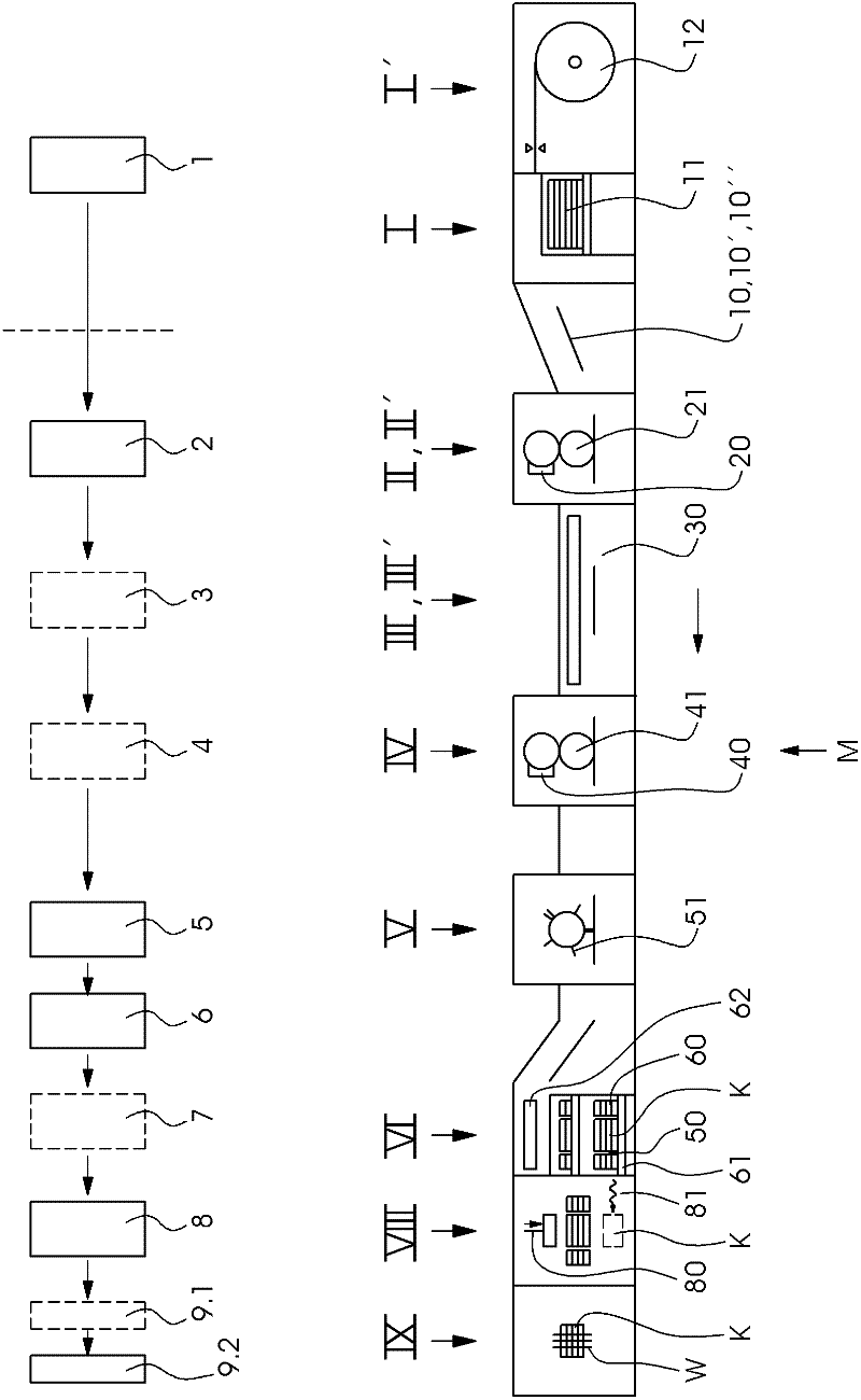
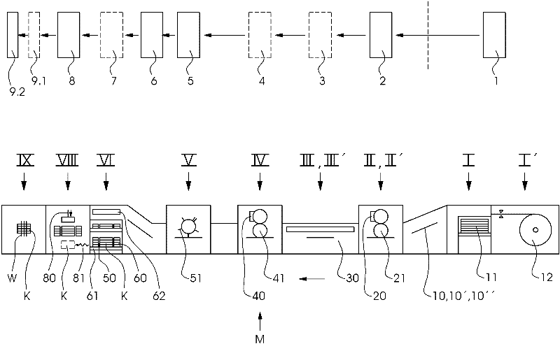
[0028] figure 1 In the upper area is shown a flow chart of a preferred embodiment of the method of the invention for producing a laminated magnetic core K or armature layers, for example from thin transformer plates, for different applications such as Transformers, motors or magnetic relays. The method can mostly be carried out in-line in a printing press processing the sheets, for example in the Speedmaster product configuration of Heidelberger Press AG (different formats, ie SM, CD, XL of the processed sheet parameters) or in Carried out in a machine consisting of parts of such a printing press. figure 1 Such a machine is shown in the lower region with an associated conveying device.

[0029] In an upstream method step 1 (singling / cross-cutting), the metal surfaces 10 are separated from the stack 11 or alternatively cross-cut by rollers 12 (electric belts). Method step 1 can be carried out in the sheet feeder I or the roll cross-cutter I' of the printing machine M which p...


PUM

PropertyMeasurementUnit
Thicknessaaaaaaaaaa

Abstract

The present invention relates to a method for producing laminated magnetic core. The magnetic core is used for a transformer or a motor. The method comprises the following steps: a paint coating step of equipping electrical insulating plant on a metal surface, particularly a metal plate or metal foil; a punching step of preferably punching the paint-coated metal surface for obtaining a jointing piece; a placing step of vertically laminating the punched metal surfaces when the laminate is formed; and a cutting-off step of cutting off the magnetic core from the laminate and cutting off the jointing piece (50). Preferably the magnetic core (K) is treated by caking / hardening step (7) before cutting (8), thereby cutting the magnetic core (K) as a whole from the laminate (60) and keeping the shape. The coated paint (20) can be treated by a drying step (3). Finally, the magnetic core (K) is provided with a winding (W). According to the invention, the magnetic core (K) can be manufactured by an ultra-thin (preferably smaller than 0.05mm) metal surface with ultra-low eddy current loss.

Description

technical field [0001] The invention relates to a method for producing a laminated magnetic core having the features of claim 1 or 2 . Furthermore, the invention relates to a machine for processing flat goods having the features of claim 10 . Background technique [0002] It is already known from the prior art to produce magnetic cores, for example for transformers or electric motors, by laminating together electrically insulating lacquered metal surfaces, for example metal sheets with a typical thickness of approximately 0.35 mm. The metal sheets are stamped into shape in a flat bed press, cut out and subsequently laminated. The method steps painting, stamping and cutting (singling) are carried out in separate stations and not in-line. [0003] One such method for manufacturing a magnetic core is disclosed by JP 57-147119 (A). Here, the metal faces are first laminated and then punched and cut ( figure 1 B). The stamped and cut away parts are finally joined into a core ...

Claims


Application Information

Patent Timeline
IPC IPC(8): H01F3/00H01F41/02
CPCH01F41/024
Inventor M·默茨
Owner HEIDELBERGER DRUCKMASHINEN AG
Why Eureka
Try Eureka