Method for calibrating parameters of motor controller without position sensor

A motor controller and parameter calibration technology, which is applied in the direction of motor generator control, electronic commutation motor control, electromechanical brake control, etc., can solve problems such as limiting performance, time-varying parameters of permanent magnet synchronous motors, and cumbersome motor control systems. Achieve the effect of improving generality and solving the problem of unidentifiable parameters

Active Publication Date: 2012-08-15
HANGZHOU ZHOUJU ELECTRONICS TECHNOLOGICAL
View PDF6 Cites 9 Cited by
  • Summary
  • Abstract
  • Description
  • Claims
  • Application Information

AI Technical Summary

Problems solved by technology

Since F. Blaschke of Siemens Corporation in Germany proposed the vector control method in 1971, this control method has been favored. However, although it solves the control problems caused by the nonlinearity of PMSM or the strong coupling of torque and flux linkage, it is not Because the parameters of the permanent magnet synchronous motor are time-varying, which limits its performance improvement in the servo system, the best way to solve this problem is to sample the permanent magnet synchronous motor in real time, and then use the sampled parameters to The motor controller is adjusted accordingly to improve the performance of the permanent magnet synchronous motor in the servo system
[0003] The motor controller parameter calibration method in the prior art is often to add additional circuits. Although the motor control system using this method can effectively solve the problem of unidentifiable parameters, the following problems still exist: due to the need to add additional circuits, especially Various sensors will change the topology of the inverter in the motor controller, making the motor control system more cumbersome

Method used


Image

  • Method for calibrating parameters of motor controller without position sensor
  • Method for calibrating parameters of motor controller without position sensor
  • Method for calibrating parameters of motor controller without position sensor

Examples


Embodiment Construction

[0038] The present invention will be further described below in conjunction with the accompanying drawings and specific embodiments.

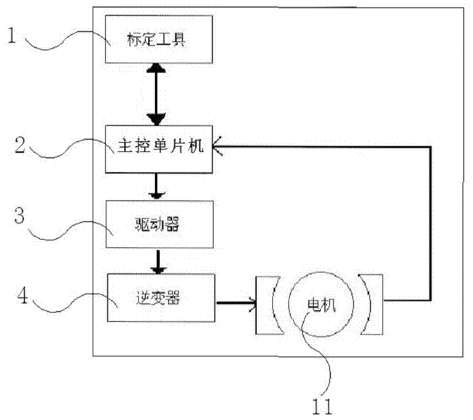
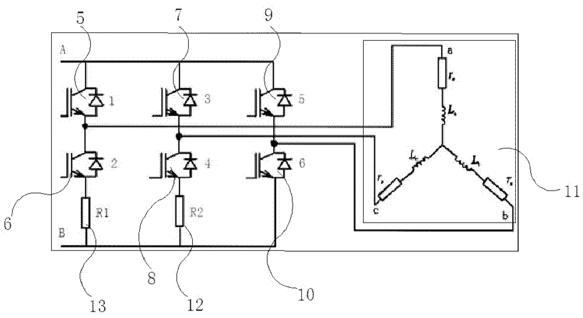
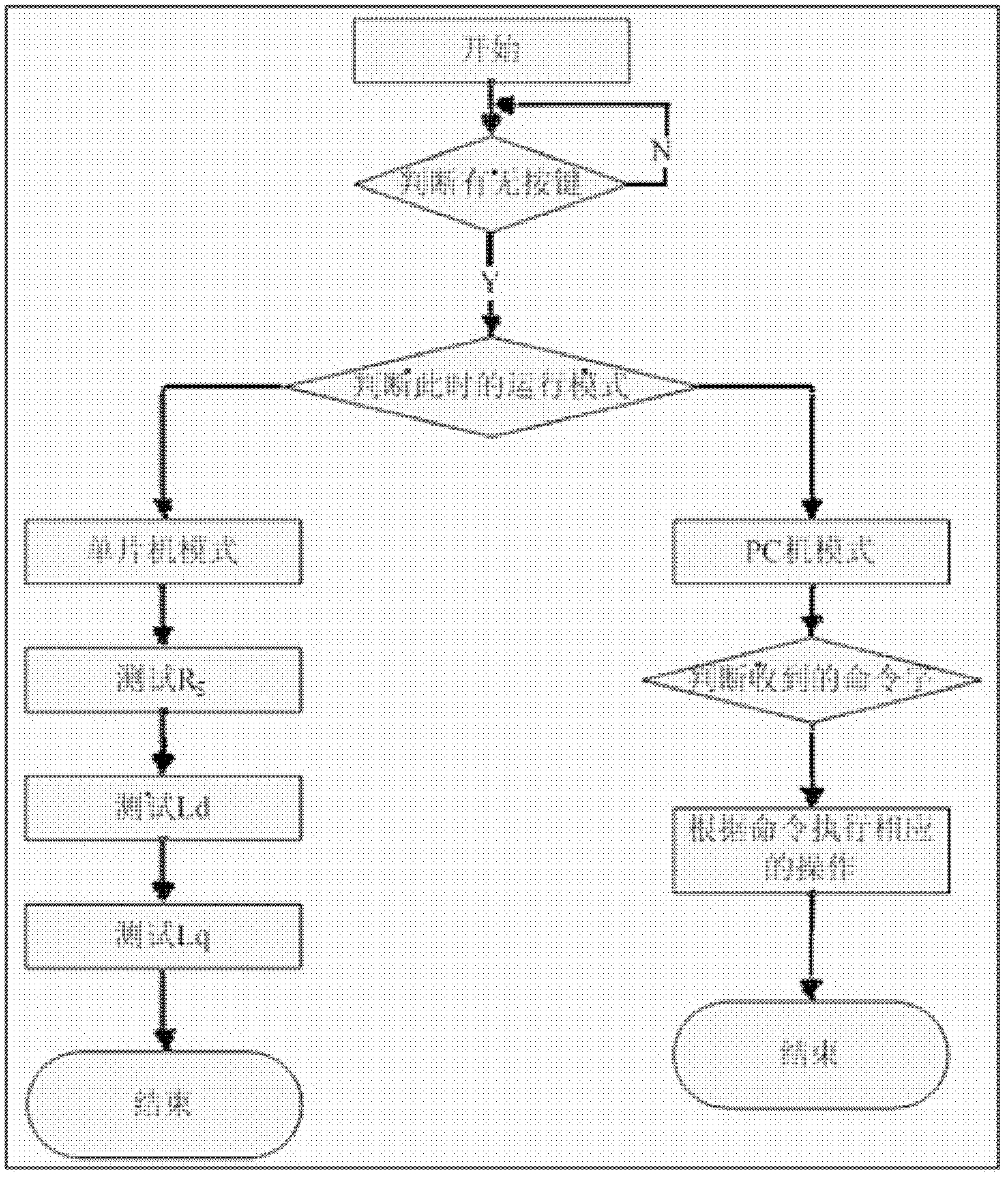
[0039] Such as figure 1 As shown, a sensorless motor controller parameter calibration method of the present invention, the system for realizing the calibration method includes a calibration tool 1, a main control microcontroller 2, a driver 3, an inverter body 4, and the first insulation of the inverter gate bipolar transistor 5, second insulated gate bipolar transistor 6, third insulated gate bipolar transistor 7, fourth insulated gate bipolar transistor 8, fifth insulated gate bipolar transistor 9, sixth insulated gate bipolar transistor Gate bipolar transistor 10, motor 11, first resistor 12 and second resistor 13, its specific steps are as follows:

[0040] Step 1, the calibration tool 1 sends a calibration command to the main control microcontroller 2 through the controller local area network bus;

[0041] Step 2, the main control microc...


PUM


Abstract

The invention discloses a method for calibrating parameters of a motor controller without a position sensor. The second step of the method includes connecting a first insulated gate bipolar transistor, a fourth insulated gate bipolar transistor, a first resistor and a motor with a power supply in series, conducting pulse width modulation pulse to the first insulated gate bipolar transistor and a second insulated gate bipolar transistor, keeping the lower arm of the second insulated gate bipolar transistor unobstructed so that voltage input at two ends of the motor is product of direct-current bus voltage U and pulse width modulation duty ratio D, testing the first resistor to obtain the value of current I, calculating end resistance of the motor by the U and the I, and dividing the end resistance to calculate stator resistance Rs. The calculation method is shown as follow. By the method for calibrating parameters of the motor controller without the position sensor, topological structure of an inverter of the motor controller cannot be changed.

Description

Technical field: [0001] The invention relates to the technical field of motor automatic control, in particular to a method for calibrating parameters of a position sensorless motor controller. Background technique: [0002] In recent years, with the rapid development of power electronics technology, microelectronics technology, new motor control theory and rare earth permanent magnet materials, permanent magnet synchronous motors have been rapidly popularized and applied. They have the advantages of small size, low loss and high efficiency. Today, energy and environmental protection are getting more and more attention, so it is very necessary to research and control them. For the control of permanent magnet synchronous motors, there are mainly constant voltage-frequency ratio control, vector control and direct torque control. Among them, vector control is the most widely used. The basic idea of ​​vector control is: in the ordinary three-phase AC The control law of DC motor ...

Claims


Application Information

Patent Timeline
Patent Type & Authority Applications(China)
IPC IPC(8): H02P21/14H02P21/16
Inventor 杨阳韩元飞徐世文
Owner HANGZHOU ZHOUJU ELECTRONICS TECHNOLOGICAL
Why Eureka
Try Eureka