Check patentability & draft patents in minutes with Patsnap Eureka AI!

Experimental immersed projective lithography objective lens

A projected light and immersion technology, which is applied in the field of high-resolution projection lithography objective lens, can solve the problems of complex structure of total refraction lithography projection objective lens, low-frequency contrast reduction, long system length, etc., and achieve simple structure and high numerical aperture. , Guarantee the effect of image quality

Active Publication Date: 2012-08-22
BEIJING INSTITUTE OF TECHNOLOGYGY
View PDF4 Cites 2 Cited by
  • Summary
  • Abstract
  • Description
  • Claims
  • Application Information

AI Technical Summary

Problems solved by technology

[0004] Among them, the total refraction lithography projection objective lens made of fused silica material is extremely sensitive to the line width of the light source; the high numerical aperture total refraction lithography projection objective lens made of fused silica material and calcium fluoride material has a complex structure. In order to ensure its working bandwidth, Using two kinds of materials to achromatize, resulting in more lenses, longer total system length and higher cost
The existing Newtonian catadioptric projection lithography objective lens has a relatively large working bandwidth, but its central obscuration is too large, resulting in a significant decrease in the low-frequency contrast of the objective image.
Existing Schwarzschild catadioptric projection lithography objectives such as figure 1 As shown, it uses fewer lenses, has a certain working bandwidth, and a smaller central obscuration, but the numerical aperture of the lithography projection objective lens is only between 0.5 and 1.05, and the resolution is limited

Method used


Image

  • Experimental immersed projective lithography objective lens
  • Experimental immersed projective lithography objective lens
  • Experimental immersed projective lithography objective lens

Examples


Embodiment Construction

[0034] In order to better illustrate the purpose and advantages of the present invention, the present invention will be further described below in conjunction with the accompanying drawings and specific embodiments.

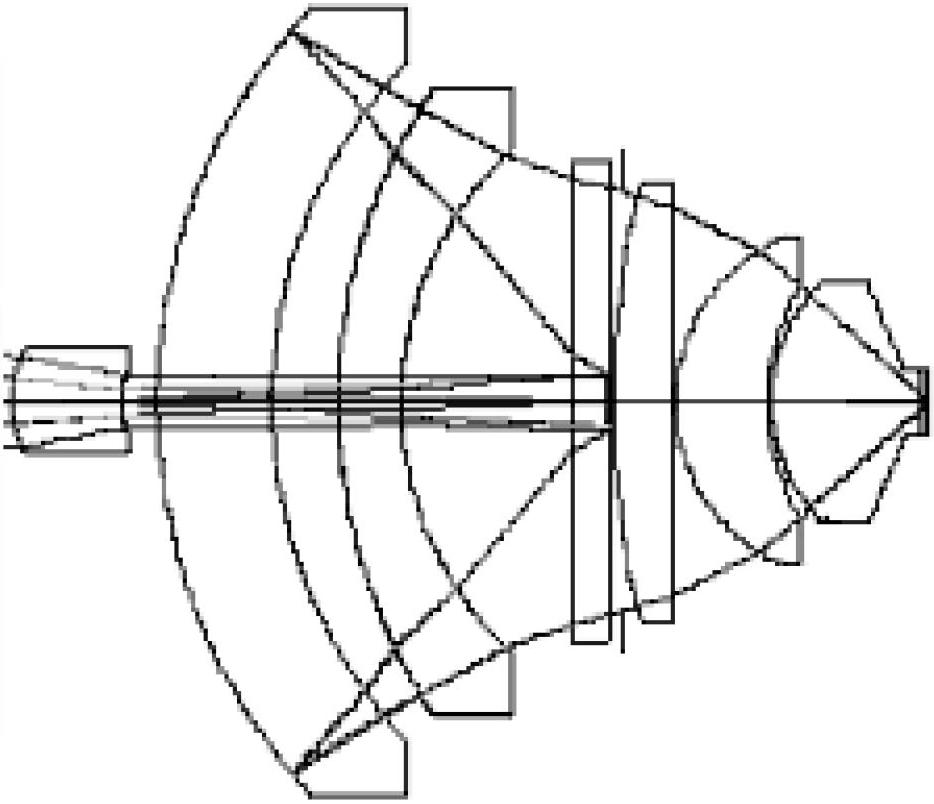
[0035] An experimental immersion projection lithography objective lens of the present invention comprises a first positive lens L1, a second Mankin concave mirror L2, a diaphragm, and a third Mankin lens arranged in sequence on the same optical axis from the mask plate to the photolithography surface. Gold convex mirror L3, the fourth meniscus lens L4, the fifth meniscus lens L5, the sixth meniscus lens L6, the seventh meniscus lens L7, the eighth plano-convex lens L8 and the ninth deionized water layer L9, wherein:

[0036] The second Mankin concave mirror L2 and the third Mankin convex mirror L3 form a Schwarzschild reflective structure, which is used to improve the image-side numerical aperture of the lithography system and ensure a working bandwidth of 70pm; ...


PUM

PropertyMeasurementUnit
Radius of curvatureaaaaaaaaaa
Clear apertureaaaaaaaaaa

Abstract

The invention discloses an experimental immersed projective lithography objective lens, wherein a dioptric lens set consisting of a Schwarzschild refracting-reflecting structure with a larger relative aperture and three pieces of meniscus lenses is adopted, so that the numerical aperture of a system can be improved to 1.20, and the lithography resolution ratio can be improved; the negative petzval field curvature generated by the Schwarzschild refracting-reflecting structure is balanced by the meniscus lenses, so that an image field can be flattened and an image space view field can be enlarged; the high-level aperture positive spherical aberration and the residual negative coma aberration remained by an eighth planoconvex lens L8 correction system with a 10-order aspheric surface are adopted, so that the numerical aperture can be improved, and the imaging quality of a lithography system can be guaranteed; and the whole set of system only uses 8 lenses, so that the structure is simple and compact, the imaging quality can be guaranteed, and the production cost can be reduced.

Description

technical field [0001] The invention relates to the technical field of high-resolution projection lithography objective lens, in particular to an experimental deep ultraviolet immersion lithography objective lens. Background technique [0002] Before the successful development of complex and expensive industrial immersion ArF lithography equipment, the research and development of many key technologies needs to be carried out on micro-miniature experimental prototypes, so as to shorten the research and development cycle and cost, and more effectively support industrial lithography machine development. [0003] The ultra-high resolution experimental immersion lithography objective lens is a key component in the immersion lithography experimental platform. At present, Nikon in Japan, Corning in the United States and other companies have disclosed experimental lithography objectives, including: small field of view total refraction projection lithography objectives, Schwarzschil...

Claims


Application Information

Patent Timeline
IPC IPC(8): G02B13/18G02B13/22G02B13/00G02B17/08G03F7/20
Inventor 李艳秋胡大伟刘晓林
Owner BEIJING INSTITUTE OF TECHNOLOGYGY
Features
  • R&D
  • Intellectual Property
  • Life Sciences
  • Materials
  • Tech Scout
  • Unparalleled Data Quality
  • Higher Quality Content
  • 60% Fewer Hallucinations
Learn More