Control device of spark-ignition gasoline engine

A gasoline engine, spark ignition technology, applied in the direction of spark ignition controller, engine control, automatic control of electric engine control, etc., can solve problems such as abnormal combustion

Inactive Publication Date: 2012-08-29
MAZDA MOTOR CORP
View PDF7 Cites 45 Cited by
  • Summary
  • Abstract
  • Description
  • Claims
  • Application Information

AI Technical Summary

Problems solved by technology

However, an engine whose geometric compression ratio is set relatively high for the purpose of stabilizing compression ignition combustion may cause ab

Method used


Image

  • Control device of spark-ignition gasoline engine
  • Control device of spark-ignition gasoline engine
  • Control device of spark-ignition gasoline engine

Examples


Embodiment Construction

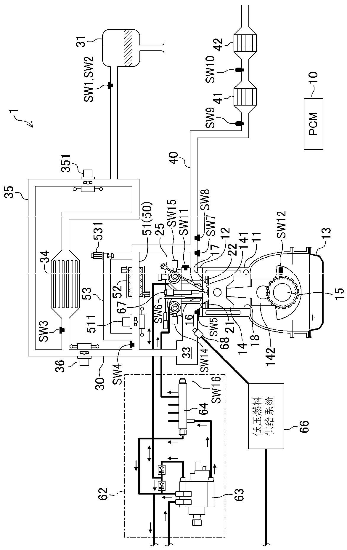
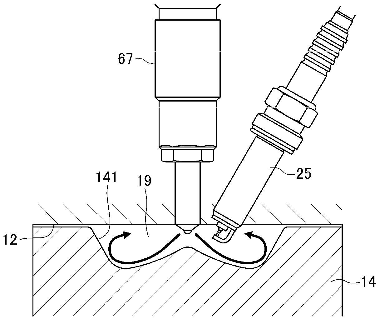
[0093] Next, an embodiment of a control device for a spark ignition type gasoline engine will be described with reference to the drawings. The description of the following preferred embodiments is an illustration. figure 1 , 2 A general structure of the engine (engine main body) 1 is shown. The engine 1 is a spark-ignition gasoline engine mounted on a vehicle and supplied with fuel containing at least gasoline. The engine 1 has a cylinder block 11 provided with a plurality of cylinders 18 (only one is shown), a cylinder head 12 arranged on the cylinder block 11, and a lower side of the cylinder block 11 for storing lubricating oil. The oil pan 13. A piston 14 connected to the crankshaft 15 via a connecting rod 142 is reciprocally inserted into each cylinder 18 . On the top surface of the piston 14, such as image 3 As shown in the enlarged representation of , the cavity 141 is formed in a reentrant shape. The chamber 141 faces the direct injection injector 67 described b...


PUM


Abstract

The disclosure provides a control device of a spark-ignition gasoline engine. According to the invention, in a spark-ignition gasoline engine (1) with a higher high compression ratio, abnormal burning in a high load area can be avoided. When an operating state of an engine body is within a low engine speed range, a controller (PCM 10) operates a fuel pressure variable mechanism (a high pressure fuel supply system 62) so that a fuel pressure is higher within a high engine load range compared to a low engine load range, the controller operates, within the high engine load range, a fuel injection mechanism to perform at least a fuel injection into the cylinder by a cylinder internal injection valve (a straight spray injector 67) at a timing during a retard period from a late stage of a compression stroke to an early stage of an expansion stroke, and the controller (10) operates, within the high engine load range, an ignition plug to ignite at a timing during the retard period and after the fuel injection.

Description

technical field [0001] The technology disclosed herein relates to control devices for spark ignition gasoline engines. Background technique [0002] In improving the theoretical thermal efficiency of spark ignition gasoline engine, increasing its geometric compression ratio is an effective method. For example, Patent Document 1 describes a spark ignition direct injection engine having a geometric compression ratio of 14 or higher and a high compression ratio. [0003] Also, as described in Patent Document 2, for example, as a technique capable of achieving both improvement of exhaust emissions and improvement of thermal efficiency, a combustion method of compression-igniting lean mixture gas is known. In an engine that performs such compression ignition combustion, increasing the geometric compression ratio contributes to the stabilization of compression ignition combustion by increasing the compression end pressure and the compression end temperature. [0004] Patent Docu...

Claims


Application Information

Patent Timeline
IPC IPC(8): F02D41/02F02D41/30
CPCF02D21/08F02D35/02F02D35/027F02D37/02F02D41/0002F02D41/0057F02D41/1441F02D41/1456F02D41/18F02D41/3023F02D41/3029F02D41/3041F02D41/3094F02D41/3836F02D41/401F02D41/402F02D2041/001F02D2200/021F02D2200/0406F02D2200/0414F02D2200/101F02D2200/602F02M45/02F02M63/0225F02M69/046F02P5/045F02P5/152F02M26/23Y02T10/40
Inventor 岩井浩平山川正尚太田统之长津和弘养祖隆渡边一丰栗田宽之渡边直哉长野高皓大场秀儿
Owner MAZDA MOTOR CORP
Why Eureka
Try Eureka