
Device and method for correcting wave aberration

A technology of a correction device and a correction method, which is applied in the field of wave aberration correction, can solve complex problems, achieve long service life, reduce driving devices and movable lenses, and reduce costs

Active Publication Date: 2014-10-29
SHANGHAI MICRO ELECTRONICS EQUIP (GRP) CO LTD
View PDF7 Cites 0 Cited by
  • Summary
  • Abstract
  • Description
  • Claims
  • Application Information

AI Technical Summary

Problems solved by technology

[0004] The technical problem solved by the invention is that the wave aberration correction of the existing projection objective lens is realized by a movable lens, and its structure is complex and the operation is complicated

Method used


Image

  • Device and method for correcting wave aberration
  • Device and method for correcting wave aberration
  • Device and method for correcting wave aberration

Examples


Embodiment Construction

[0040] Specific embodiments of the present invention will be described in detail below with reference to the drawings.

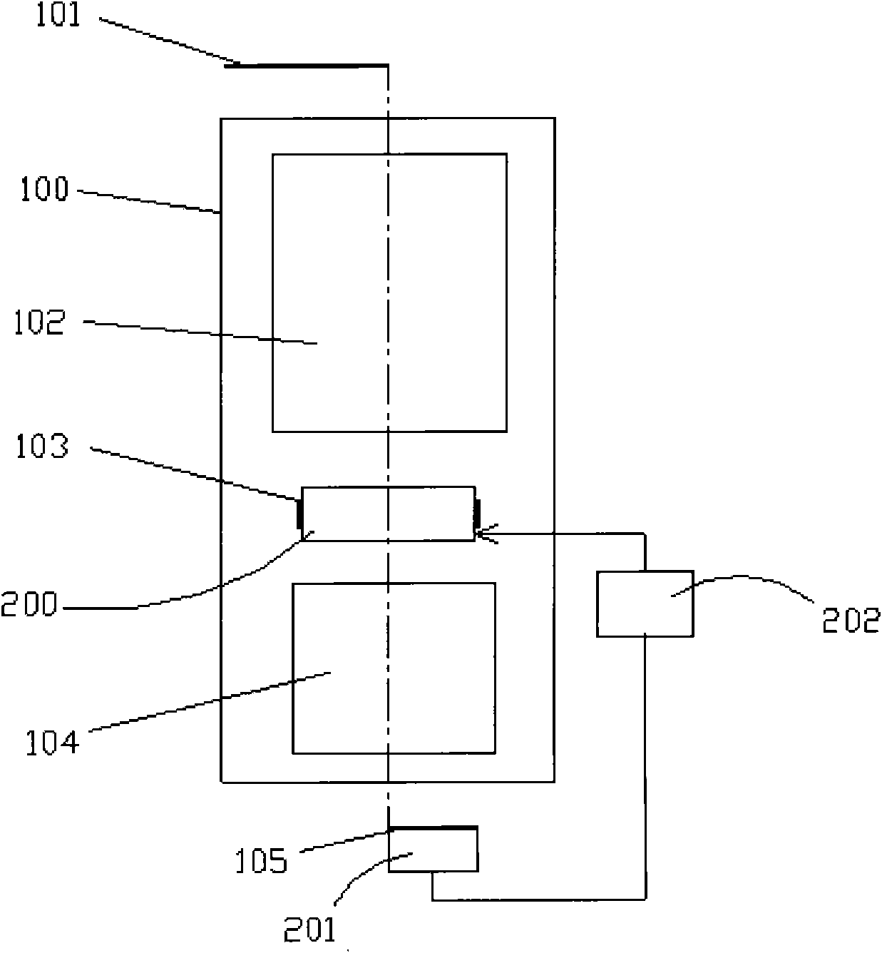
[0041] The wave aberration correction device and its projection objective lens structure used in the present invention are as follows figure 1 As shown, the projection objective 100 is composed of optical refracting lens groups 102, 104, an aperture stop 103, and a liquid lens 200. Light incident from the object surface 101 passes through the refracting lens group 102, the aperture stop 103, the liquid lens 200, and the refracting lens group. 104 exits to the image surface 105.

[0042] The wave aberration correction device includes a liquid lens 200, a wave aberration measurement system 201, and a signal processing system 202.

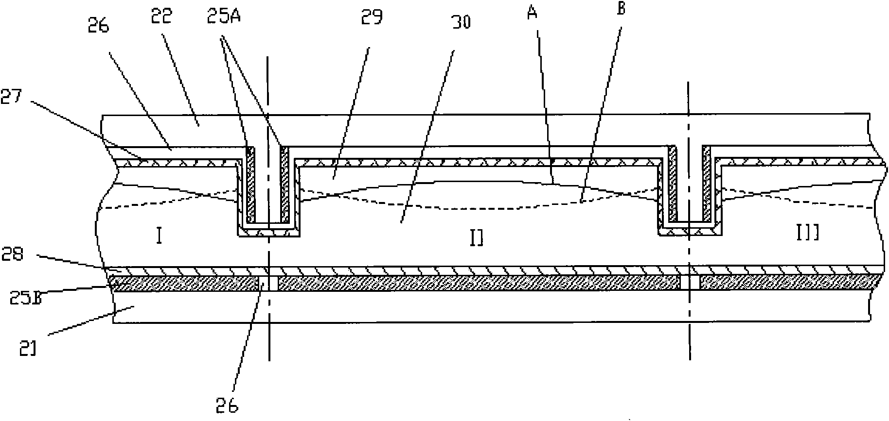
[0043] The structure of the liquid lens 200 is as figure 2 As shown, the liquid lens is a liquid lens array. The shape of the liquid lens array is circular, the diameter is determined according to the diameter of the aperture diaphragm, ...


PUM

PropertyMeasurementUnit
diameteraaaaaaaaaa

Abstract

The invention relates to a wave aberration correcting device and method. The correcting device comprises a wave aberration measuring system, a signal processing system and a liquid lens, wherein the wave aberration measuring system is used for measuring wave aberration of a projection objective, the signal processing system is used for processing the wave aberration of the projection objective and outputting a driving voltage signal, and the liquid lens is used for generating deformation according to the driving voltage signal and carrying out wave aberration correction on the projection objective. The correcting method comprises the following steps: the wave aberration measuring system measures the wave aberration on an image plane, calculates deviation of the wave aberration of the projection objective and a required value, fits the deviation into a wavefront error and sends the wavefront error to the signal processing system; the signal processing system converts the received wavefront error into deformation deviation of the liquid lens and outputs a driving direct current voltage according to the deformation deviation of the liquid lens; and the driving direct current voltage causes the liquid lens to deform. The wave aberration correcting device and correcting method disclosed by the invention can realize correction on the wave aberration of the projection objective, and the correcting device disclosed by the invention is simple in structure, low in cost, easy in operation and long in service life.

Description

Technical field [0001] The present invention relates to the field of wave aberration correction, in particular to a wave aberration correction device and method applied to a projection objective lens of a photolithography device. Background technique [0002] The wave aberration of the projection objective lens is an important factor that affects the engraving accuracy and lithography resolution of the lithography machine. With the continuous decrease of the lithography feature size CD, the influence of wave aberration on the image quality of lithography becomes more and more prominent. During the use of the lithography machine, thermal effects, processing stress release, exposure process changes, changes in the external environment, etc. will cause the wave aberration to change. Once the wave aberration changes, it will affect the imaging quality and the wafer yield. Therefore, the correction of the wave aberration of the projection objective lens of the lithography machine beco...

Claims


Application Information

Patent Timeline
Patent Type & Authority Patents(China)
IPC IPC(8): G03F7/20
Inventor 段立峰李映笙马明英
Owner SHANGHAI MICRO ELECTRONICS EQUIP (GRP) CO LTD
Learn More