
Double-channel axial magnetic circuit outer rotor reluctance type rotary transformer

A rotary transformer and axial magnetic circuit technology, applied in the field of rotary transformers, can solve problems such as small output and input impedance, increase in resolver diameter, and load performance degradation, so as to improve load performance, reduce potential constant components, and eliminate errors Effect

Active Publication Date: 2012-09-12
HARBIN INST OF TECH
View PDF5 Cites 8 Cited by
  • Summary
  • Abstract
  • Description
  • Claims
  • Application Information

AI Technical Summary

Problems solved by technology

[0003] The present invention adopts the outer rotor structure, which is used in mechanical structures that require external rotation, such as electric vehicles, and can solve the problem that the existing reluctance rotary transformer has a large air gap, and the output and input impedances are small, which causes the load performance to drop
At the same time, when the number of pole pairs increases to a certain value, it is necessary to increase the diameter correspondingly, which leads to the problem of increasing the diameter of the resolver, and then provides a dual-channel axial magnetic circuit outer rotor reluctance resolver

Method used


Image

  • Double-channel axial magnetic circuit outer rotor reluctance type rotary transformer
  • Double-channel axial magnetic circuit outer rotor reluctance type rotary transformer
  • Double-channel axial magnetic circuit outer rotor reluctance type rotary transformer

Examples


Embodiment Construction

[0012] The present invention will be described in further detail below in conjunction with the accompanying drawings: the present embodiment is implemented on the premise of the technical solution of the present invention, and detailed implementation is provided, but the protection scope of the present invention is not limited to the following embodiments.

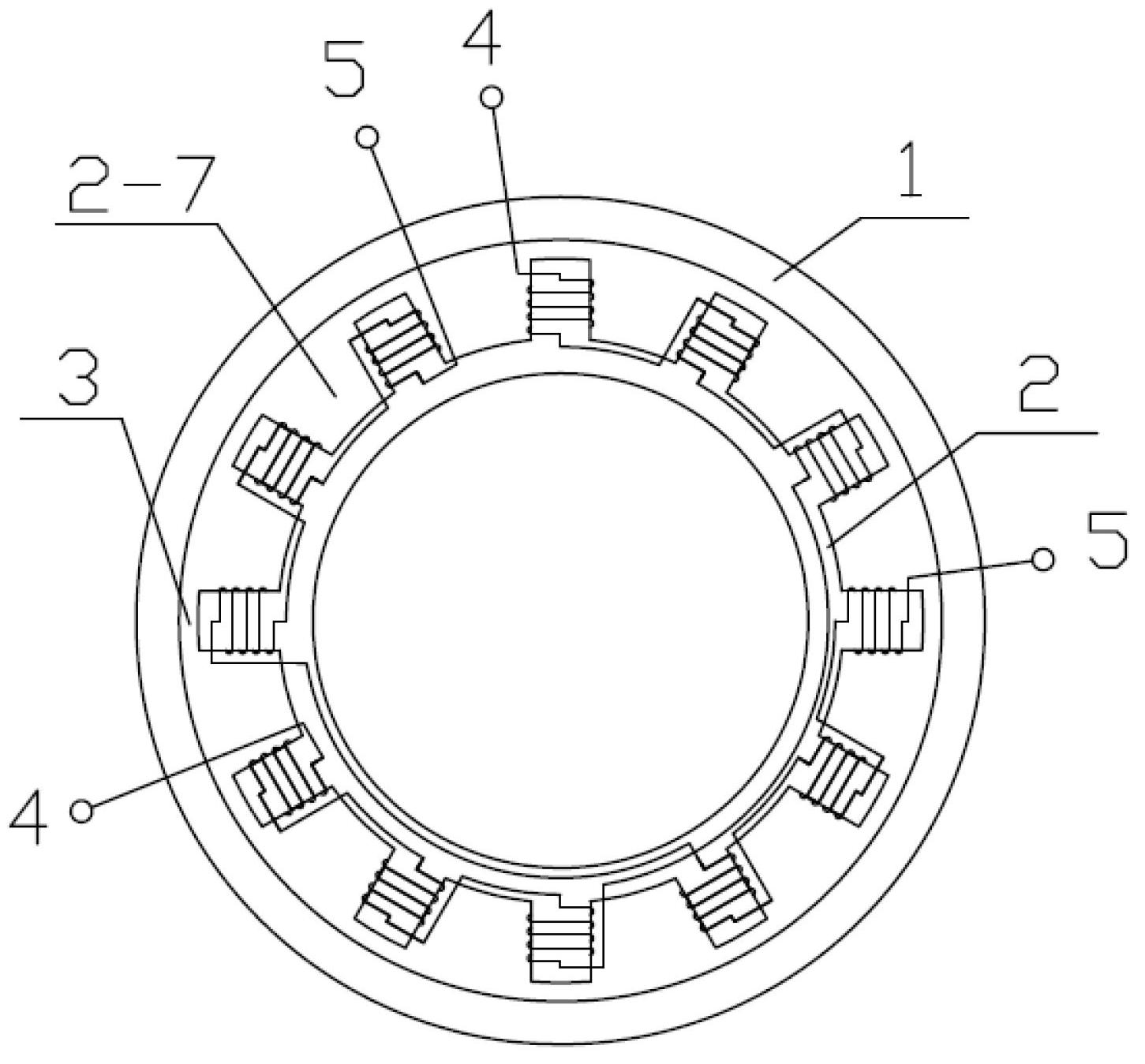
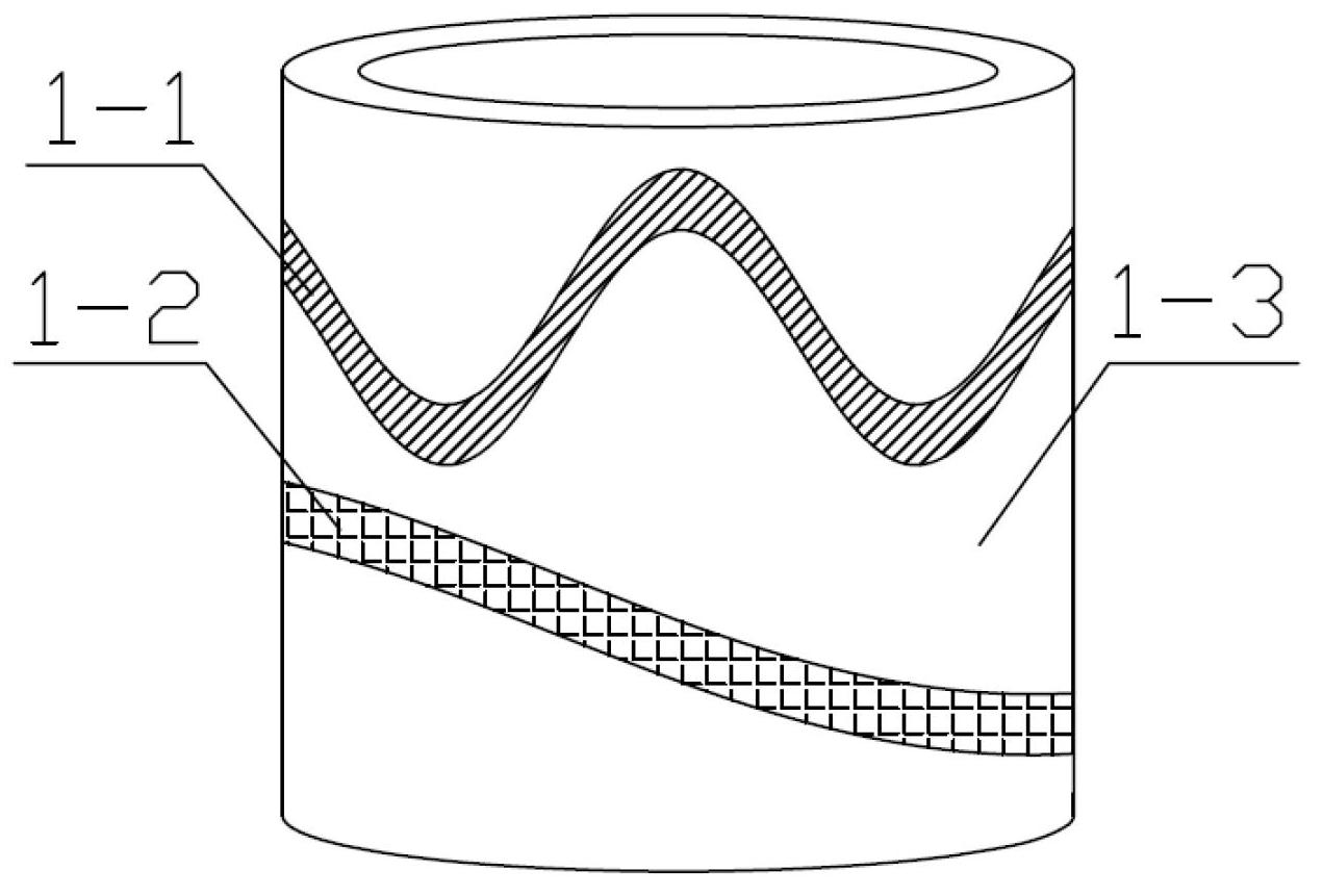
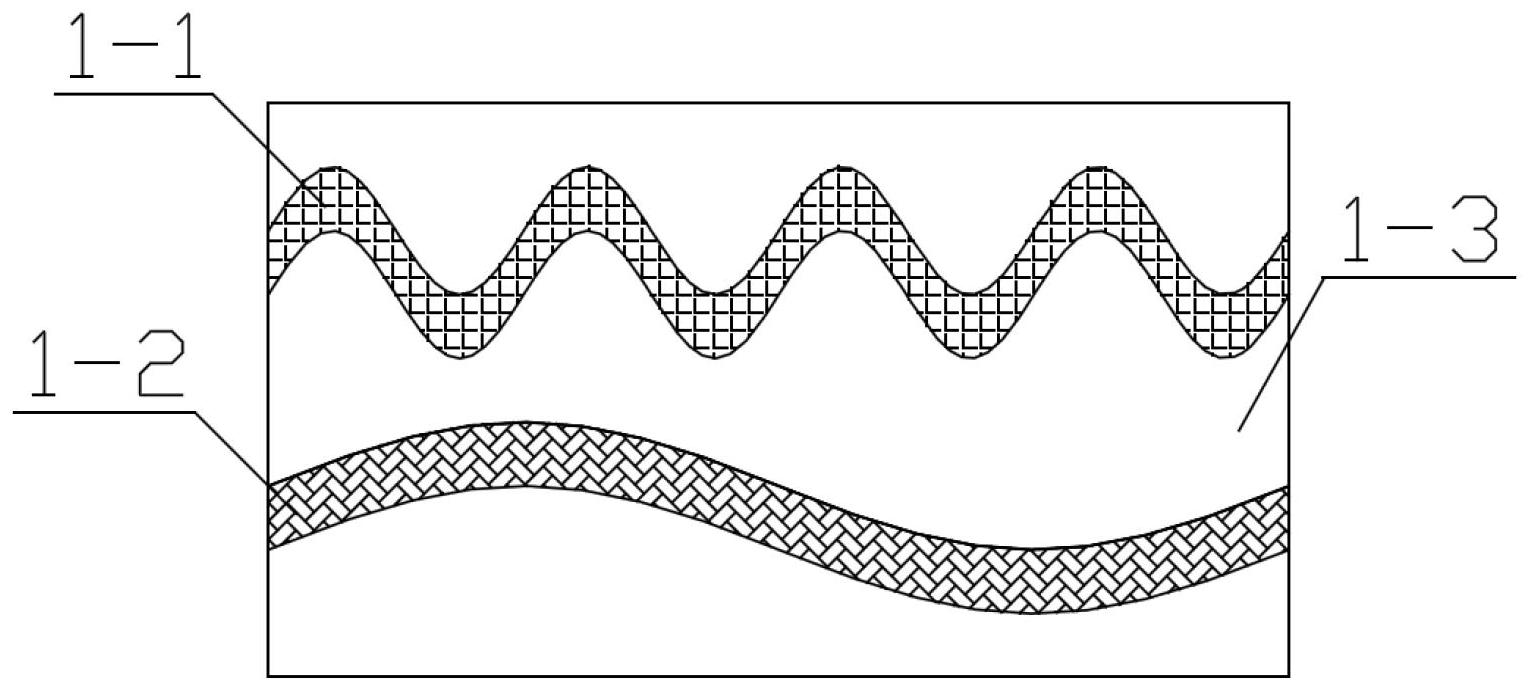
[0013] Such as Figure 1~Figure 5 As shown, a dual-channel axial magnetic circuit outer rotor reluctance rotary transformer involved in this embodiment includes: a rotor 1 and a stator 2, and also includes a first phase signal winding 4, a second phase signal winding 5, an excitation Winding 6 and sine-cosine signal winding 7; There is air gap 3 between described rotor 1 and stator 2; Composed of conductive tape 1-2 and non-magnetic rotor bracket 1-3, multi-pole fine machine corrugated conductive tape 1-1 and single-pole coarse machine corrugated conductive tape 1-2 are distributed along the circumferential direction of ro...


PUM

PropertyMeasurementUnit
Lengthaaaaaaaaaa

Abstract

The invention provides a double-channel axial magnetic circuit outer rotor reluctance type rotary transformer, belonging to the technical field of rotary transformers. A rotor of the double-channel axial magnetic circuit outer rotor reluctance type rotary transformer provided by the invention has two layers of magnetic conduction materials, the two layers of the magnetic conduction materials are distributed according to the sine law, and the cycles of formed sine waves are different. A stator corresponding to the rotor is also divided into two layers, namely a roughing machine stator and a finishing machine stator. An excitation winding and two phases of signal windings are arranged on the stator in an orthogonal manner, and the winding is not arranged on the rotor. When the excitation winding is conducted by alternating current with constant voltage and frequency, the two phases of the signal windings can respectively output voltage with electromotive force amplitudes which can perform sine and cosine changes along with the rotation angle of the rotor. The outer rotor axial magnetic circuit double-channel reluctance type rotary transformer has a simple and compact structure, and can not only reduce an electromotive force constant component, but also eliminate the error caused by installation eccentricity and the like to the greatest extent so as to further improve the measurement precision. The double-channel axial magnetic circuit outer rotor reluctance type rotary transformer provided by the invention is especially suitable for speed and position sensors of servo systems.

Description

technical field [0001] The invention relates to a dual-channel axial magnetic circuit outer rotor reluctance rotary transformer, which belongs to the technical field of rotary transformers. Background technique [0002] The reluctance multi-pole resolver is suitable for high-precision position closed-loop systems due to its high position measurement accuracy, good anti-vibration performance, and strong anti-electromagnetic interference ability. It is used in various fields as a position and speed sensor for closed-loop. The reluctance rotary transformer is developed from the traditional rotary transformer. It not only realizes brushless, but also further simplifies the structure and solves the problem of excitation structure. Existing reluctance resolvers generally adopt a radial magnetic circuit variable reluctance structure: that is, the variable reluctance design is performed by changing the length of the air gap, and then the potential amplitude of the output signal is c...

Claims


Application Information

Patent Timeline
IPC IPC(8): H01F38/18H01F27/28H02K1/22H02K1/12H02K3/46
Inventor 尚静王昊王伟强江善林邹继斌胡建辉
Owner HARBIN INST OF TECH
Learn More