
Arrayed photoelectric detector in wireless laser communication device

A technology of photodetector and communication device, applied in the direction of free space transmission, etc., can solve the problems of difficulty in ensuring normal reception of optical communication signals, bulky servo tracking system and high cost, etc.

Inactive Publication Date: 2015-03-18
CHANGCHUN UNIV OF SCI & TECH
View PDF3 Cites 0 Cited by
  • Summary
  • Abstract
  • Description
  • Claims
  • Application Information

AI Technical Summary

Problems solved by technology

[0004] However, the existing servo tracking system is used in the seat type wireless laser communication system. The servo tracking system is bulky, heavy, complex and precise, and has a high cost. Small mechanical bandwidth, which leads to a reduction in the control bandwidth and control accuracy of the wireless laser communication system
What's more, this mechanical alignment and tracking method is difficult to be suitable for portable wireless laser communication systems
In fact, the existing portable wireless laser communication system can only rely on the aiming device for alignment and tracking. In view of the above-mentioned relationship between the frequency response bandwidth, the area of ​​the photosensitive surface, and the diaphragm of the field of view, it is difficult for the sighting device to ensure that the light Normal reception of communication signals, optical communication is difficult to carry out normally

Method used


Image

  • Arrayed photoelectric detector in wireless laser communication device
  • Arrayed photoelectric detector in wireless laser communication device
  • Arrayed photoelectric detector in wireless laser communication device

Examples


Embodiment Construction

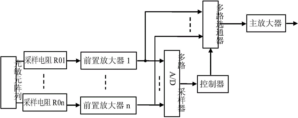
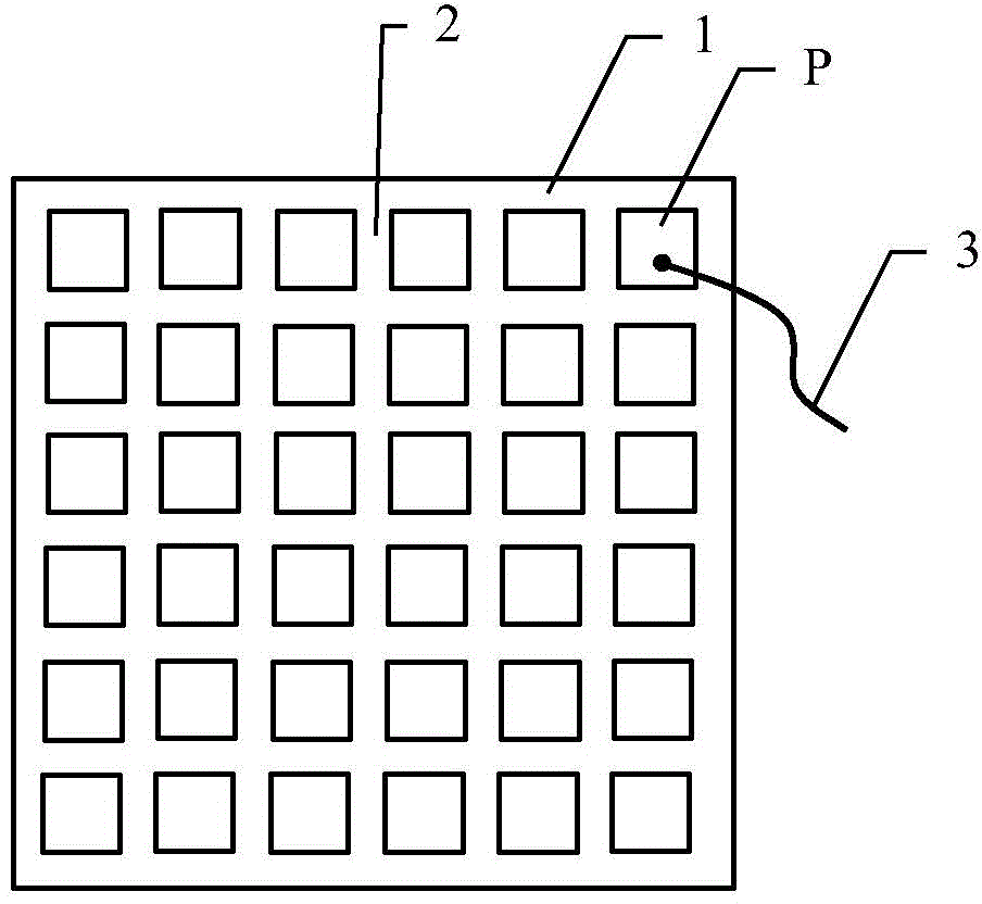
[0011] The array photodetector in the wireless laser communication device of the present invention consists of a photosensitive element P connected in series with a sampling resistor R0 to form a transimpedance detector, and the detected optical power and voltage signals are sequentially amplified by a preamplifier and a main amplifier, see figure 2 shown. Several photosensitive elements P are arranged on the metal substrate 1 to form a photosensitive element array, and the number of photosensitive elements P is 2×2~10×10, such as 6×6, see image 3 As shown, the photosensitive elements P are electrically isolated by the air groove 2, and the metal substrate 1 serves as the common ground of each photosensitive element P, which can reduce the static noise of the array photodetector. One of the specific schemes of the photosensitive element array is that several discrete element photodiodes are arranged as photosensitive elements P, and the other is integrated manufacturing on t...


PUM


Abstract

The invention discloses an arrayed photoelectric detector in a wireless laser communication device, belonging to the technical field of wireless laser communication. In consideration of a restriction relation among a frequency response bandwidth, a photosensitive surface area and an eyesight diaphragm, the prior art requires the existence of a precise mechanical servo tracking system. According to the invention, a transimpedance detector is formed by a photosensitive element P and a sampling resistor R0 which are connected in series; a detected optical power voltage signal is amplified by a prepositioned amplifier and a master amplifier in turns; a plurality of the photosensitive elements P are arrayed to form a photosensitive element array; each photosensitive element P together with one sampling circuit R0 forms one transimpedance detector; and each transimpedance detector is connected with the prepositioned amplifier; an output end of each prepositioned amplifier is divided into two paths to be respectively connected with a multipath A / D (analogue-to-digital) sampler and a multipath gating device; a controller is connected between the multipath A / D sampler and the multipath gating device; and the output end of the multipath gating device is connected with the main amplifier. The detector is applied to a portable wireless laser communication system, realizes synchronous receiving and tracking of laser communication signals, and adopts a photoelectric tracking way.

Description

technical field [0001] The invention relates to an array photodetector in a wireless laser communication device, belonging to the technical field of wireless laser communication. Background technique [0002] Wireless laser communication refers to optical communication that uses laser waves as the carrier and the atmosphere as the transmission medium. Compared with microwave communication, laser communication has the characteristics of large information capacity, wide frequency band, strong anti-electromagnetic interference ability, and good confidentiality. Compared with wired and optical fiber communication, it has the advantages of flexibility, little impact on municipal construction, low operating cost, and easy promotion. Laser communication does not occupy radio spectrum resources, does not need to apply for a frequency license, and does not need to dig roads for laying pipelines. It is flexible to erect and can complete various communication tasks that cannot be acco...

Claims


Application Information

Patent Timeline
Patent Type & Authority Patents(China)
IPC IPC(8): H04B10/11
Inventor 李锦青柏逢明底晓强李平王贺管红梅祁晖从立刚魏枫林尚瑞瑞
Owner CHANGCHUN UNIV OF SCI & TECH
Learn More