Ion beam certainty adding device applied in ion beam polishing process and ion beam polishing system

A technology of adding device and ion beam, applied in the field of ion beam deterministic adding device and ion beam polishing system, can solve the problem that it is difficult to achieve uniform convergence of full-frequency surface error and large gradient error removal processing, and it is difficult to realize large error gradient removal processing, It is difficult to remove the error low point and other problems to achieve the effect of improving surface roughness, simple structure and continuation performance

Active Publication Date: 2014-06-25
NAT UNIV OF DEFENSE TECH
View PDF6 Cites 4 Cited by
  • Summary
  • Abstract
  • Description
  • Claims
  • Application Information

AI Technical Summary

Problems solved by technology

It is difficult to remove the low point of error in the processing of nanometer precision, and it is difficult to realize the removal processing of large error gradient
In order to solve this problem, it usually needs to be combined with other processing techniques, but it cannot guarantee the surface shape accuracy of other areas while removing large gradient errors, and the required processing time will be greatly increased
[0008] Therefore, the ion beam polishing method based on the removal of a single error high point has been difficult to achieve the consistent convergence of the full-frequency surface shape error and the removal of large gradient errors. At present, there is no effective solution to the above-mentioned high-precision optical mirror processing. The processing technology of the problem

Method used


Image

  • Ion beam certainty adding device applied in ion beam polishing process and ion beam polishing system
  • Ion beam certainty adding device applied in ion beam polishing process and ion beam polishing system
  • Ion beam certainty adding device applied in ion beam polishing process and ion beam polishing system

Examples


Embodiment

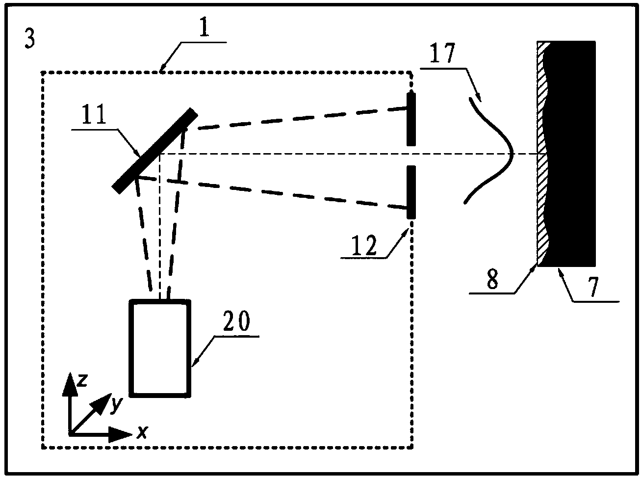
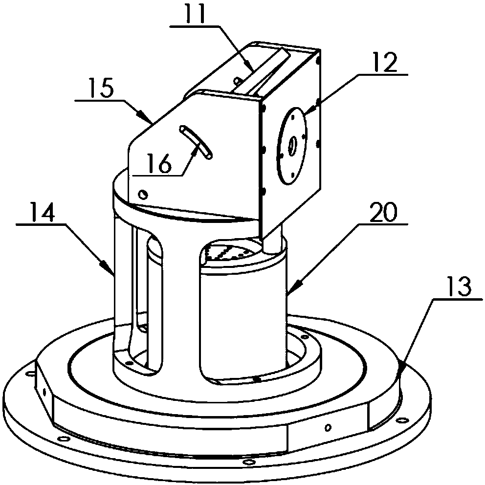
[0040] a kind of like figure 1 and figure 2 The shown ion beam deterministic adding device applied to the ion beam polishing process, the ion beam deterministic adding device 1 includes a support frame 14, an ion source 20 installed in the support frame 14 and an ion beam emitted by the ion source 20 The target material 11 to be bombarded, the support frame 14 includes a target material fixing fixture 15 for fixing the target material 11, and a fan-shaped waist-shaped hole 16 is provided on the target material fixing fixture 15, and the target material is installed in the waist-shaped hole 16 through a joint. The inclination angle of the target 11 can be adjusted through the waist hole 16 (that is, the incident angle of the ion beam can be changed). In this embodiment, the incident angle of the ion beam is 45°, and the type of the target 11 can also be changed as required. The support frame 14 is provided with an aperture 12 for intercepting the sputtering atomic flux of the...


PUM


Abstract

The invention discloses an ion beam certainty adding device applied in an ion beam polishing process. The ion beam certainty adding device comprises a support frame, an ion source and a target material bombarded by ion beams emitted from the ion source are installed in the support frame, the support frame comprises a target material fixing clamp for fixing the target material, and a diaphragm for cutting off atom flows sputtered by the target material is arranged on the support frame. A mounting flange for being installed on an ion beam polishing system is installed on the bottom portion of the support frame. The invention further discloses an ion beam polishing system which comprises a vacuum chamber, a movement system and an ion source system, wherein the movement system and the ion source system are mutually connected, an adding device is arranged in the ion beam polishing system, a clamp for a material removal process is distributed right opposite to the ion beam emission direction of the adding device, and a clamp for a material adding process is distributed right opposite to the sputtering atom flow direction of the adding device. The ion beam certainty adding device is simple in structure, convenient to manufacture and install, and capable of effectively improving surface roughness of optical elements and correcting medium-high frequency errors of an optical mirror surface.

Description

technical field [0001] The invention belongs to the technical field of ion beam polishing processing of optical elements, and in particular relates to an ion beam deterministic adding device and an ion beam polishing system. Background technique [0002] With the continuous improvement of optical system performance, the precision requirements of optical components are getting higher and higher, which poses new challenges to modern optical manufacturing technology. Taking extreme ultraviolet lithography (EUVL) technology as an example, the error mechanisms of different frequency bands of mirrors constituting the extreme ultraviolet lithography (EUVL) system have different influence mechanisms on imaging quality, and the root mean square value of the full frequency band error is required to be controlled in the sub-nanometer range , put forward the most stringent requirements for modern optical manufacturing technology. [0003] A breakthrough in the processing of modern opti...

Claims


Application Information

Patent Timeline
Patent Type & Authority Patents(China)
IPC IPC(8): B24B1/00
Inventor 戴一帆李圣怡廖文林解旭辉周林袁征
Owner NAT UNIV OF DEFENSE TECH
Why Eureka
Try Eureka