Energy-saving roller-hearth continuous kiln waste heat boiler

A waste heat boiler, continuous technology, applied in the direction of furnace, waste heat treatment, furnace components, etc., can solve the problems of large energy consumption, worse working conditions of workers, poor heat transfer effect, etc., to reduce secondary oxidation burning loss, improve external Effect of surface quality and improvement of heat recovery rate

Inactive Publication Date: 2012-09-19
HENGYANG DINGDIANER IND FURNACE ENERGY CONSERVATION
View PDF5 Cites 1 Cited by
  • Summary
  • Abstract
  • Description
  • Claims
  • Application Information

AI Technical Summary

Problems solved by technology

Its disadvantages are: the temperature of steel pipes, steel plates and strip steel products directly out of the furnace after annealing or normalizing is as high as 800°C, resulting in a large amount of high-temperature heat energy being released in the atmosphere, resulting in poor working conditions for annealing workers; at the same time, When products such as steel pipes, steel plates, and strip steel are annealed at about 800°C and air-cooled, the iron in the surface layer will chemically react with oxidizing gases (such as oxygen and water vapor) in the air to produce secondary oxidation. After the secondary oxidation of products such as steel plates, steel strips, etc., a thick layer of secondary oxide scale is formed on the surface, which affects the pickling speed of steel pipes, steel plates, and strip steel products, and increases the consumption of sulfuric acid during pickling; if When the finished steel pipe, steel plate and strip steel are annealed, the secondary oxide scale is thicker, which will not only cause the loss of steel, but also reduce the outer surface quality of steel pipe, steel plate and strip steel.
[0003] In addition, most of the high-temperature flue gas in the annealing furnace in the prior art uses an air heat exchanger for waste heat utilization, but the heat exchange effect of the air heat exchanger is poor, and it can only reduce the high-temperature flue gas at about 750°C to 500°C. ℃, there is still a large amount of heat energy in the flue gas that has not been fully utilized, and steel pipes, steel plates, and strip steel products need steam heating in the production process, and it takes a lot of energy to generate steam through coal (gas) boilers. Energy, which is not conducive to enterprises to reduce production costs and wastes national energy resources, but also causes environmental pollution and deteriorates the working conditions of workers

Method used


Image

  • Energy-saving roller-hearth continuous kiln waste heat boiler
  • Energy-saving roller-hearth continuous kiln waste heat boiler
  • Energy-saving roller-hearth continuous kiln waste heat boiler

Examples


Embodiment 1

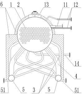
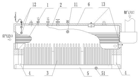
[0018] Such as figure 1 , 2 Shown: an energy-saving roller bottom continuous kiln waste heat boiler with a smoke pipe, including a smoke pipe 1, a drum 2, a heat exchange pipe 3, a downcomer 4 and a header pipe 5, and the smoke pipe 1 is located in the drum 2 Inside, there is a water inlet pipe 21, a water level gauge pipe 22 and an inspection manhole 23 on the drum 2, a sewage pipe 24 is arranged at the bottom, and the shape of the heat exchange pipe 3 is L-shaped so as to be as close as possible to the steel pipe. Afterwards, it is divided into several rows, and each row has six tubes in total. The lower parts of three heat exchange tubes 3 are connected with the left header tube 5, the lower parts of the other three heat exchange tubes 3 are connected with the right header tube 5, and the upper parts of the six heat exchange tubes 3 are connected to each other. It is connected with the drum 2; the downpipes 4 are divided into two rows in total, four in total, and the front...

Embodiment 2

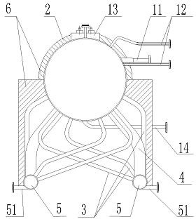
[0021] Such as image 3 , 4 Shown: an energy-saving roller bottom continuous kiln waste heat boiler without smoke tubes, including a drum 2, a heat exchange tube 3, a downcomer 4 and a header tube 5, and a water inlet pipe 21 and a water level gauge on the drum 2 Pipe 22 and maintenance manhole 23, bottom has blowdown pipe 24, and the shape of heat exchange pipe 3 is L shape, so that close to steel pipe as far as possible, heat exchange pipe 3 is divided into several rows from front to back, each row has six altogether, and wherein three The lower part of the exchange tube 3 is connected to the left header tube 5, the lower parts of the other three heat exchange tubes 3 are connected to the right header tube 5, and the upper parts of the six heat exchange tubes 3 are connected to the drum 2; There are four in total, and the front row and the rear row each have two left and right downcomers 4, the lower parts of the left and right downcomers 4 are respectively connected with t...


PUM


Abstract

The invention discloses an energy-saving roller-hearth continuous kiln waste heat boiler, which comprises a smoke pipe 1, a drum 2, heat exchange tubes 3, down pipes 4 and header pipes 5, wherein the smoke pipe 1 is positioned in the drum 2; the heat exchange tubes 3 have an L shape so as to be close to a steel pipe as much as possible; the lower parts of the heat exchange tubes 3 are respectively connected with the left and right header pipes 5, and the upper parts of the heat exchange tubes 3 are connected with the drum 2; the lower parts of the down pipes 4 are respectively connected with the left and right header pipes 5, and the upper parts of the down pipes 4 are connected with the drum 2; and thermal insulating layers 6 are arranged on the outer sides of the drum 2 and the heat exchange tubes 3 and at the peripheries of the down pipes 4 and the header pipes 5. Two kinds of heat energy, namely high-temperature smoke heat energy and radiating heat energy of the steel pipe, can be simultaneously exchanged into steam to serve as steam for production of the steel pipes and domestic steam; and moreover, the tapping temperature of the steel pipe is reduced, the secondary oxidation loss is reduced, and the outer surface quality of a product is improved.

Description

technical field [0001] The invention relates to a heat treatment furnace, in particular to an energy-saving roller bottom continuous kiln waste heat boiler. Background technique [0002] The existing steel pipe, steel plate and strip steel and other products, the roller bottom continuous annealing furnace used in the production process includes a heating room, a heat preservation room and a furnace roll, the heating room and the heat preservation room are connected, and the furnace roll passes through the bearing seat outside the furnace wall It is installed in the heating room and the heat preservation room. The upper part of the furnace wall is the furnace roof, the lower part is the furnace bottom, and there is a flue at the end of the heat preservation room. In the roller hearth continuous annealing furnace, steel pipes, steel plates and strip steel products are rapidly heated at high temperature in the heating room and kept warm in the holding room, and then they are d...

Claims


Application Information

Patent Timeline
Patent Type & Authority Applications(China)
IPC IPC(8): F22B1/18F27D17/00
CPCY02P10/25
Inventor 丁永健丁帅
Owner HENGYANG DINGDIANER IND FURNACE ENERGY CONSERVATION
Why Eureka
Try Eureka