Cascading distributed fiber Raman temperature measuring system

A distributed optical fiber, Raman temperature measurement technology, applied in thermometers, measurement devices, measurement of heat and other directions, can solve the problem of no distributed temperature measurement system, eliminate adverse effects, reduce measurement errors, and resist electromagnetic interference. strong effect

Active Publication Date: 2012-09-19
潍坊五洲浩特电气有限公司
View PDF6 Cites 8 Cited by
  • Summary
  • Abstract
  • Description
  • Claims
  • Application Information

AI Technical Summary

Problems solved by technology

[0005] Existing distributed optical fiber Raman temperature sensors such as Chinese patent CN200910102201.1 "Raman-related dual-wavelength light source self-calibration distributed optical fiber Rama

Method used


Image

  • Cascading distributed fiber Raman temperature measuring system
  • Cascading distributed fiber Raman temperature measuring system
  • Cascading distributed fiber Raman temperature measuring system

Examples


Embodiment Construction

[0018] Specific embodiments of the present invention will be described below in conjunction with the accompanying drawings, so as to better understand the present invention.

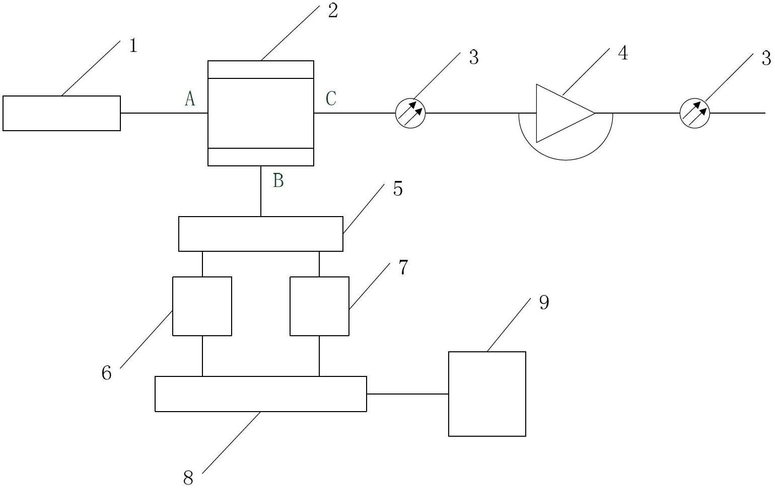
[0019] Such as figure 1 As shown, the cascadable distributed optical fiber Raman temperature measurement system of the present invention includes: a broadband light source 1, a bidirectional three-channel coupler 2, a single-mode optical fiber 3, an optical relay amplifier 4, an optical splitter 5, and a first photoelectric receiver 6 , a second photoelectric receiver 7, a signal acquisition card 8 and a computer 9; wherein the A port and the C port of the bidirectional three-channel fiber coupler 2 are respectively connected to a broadband light source 1 and a single-mode optical fiber 3, and the B port is connected to an optical splitter 5; The two ends of the amplifier 4 are respectively connected to the single-mode optical fiber 3 in sequence; the two beams of light split by the optical splitter 5 ar...


PUM

PropertyMeasurementUnit
Center wavelengthaaaaaaaaaa
Bandwidthaaaaaaaaaa

Abstract

A cascading distributed fiber Raman temperature measuring system comprises a broadband light source, a bidirectional three-channel fiber coupler, a single-mode fiber, an optical relay amplifier, an optical splitter, a first photoelectric receiver, a second photoelectric receiver, a signal acquisition card and a computer. The cascading distributed fiber Raman temperature measuring system is mainly used for measuring temperature of power transmission and distribution systems, oil well exploration, gas pipeline systems and the like, and can adapt to various measurement environments by adjustment as required during use. The cascading distributed fiber Raman temperature measuring system has the advantages of safety, reliability, high weather resistance, wide application range, long transmission distance and high electromagnetic resistance.

Description

technical field [0001] The invention belongs to the technical field of optical fiber measurement, in particular to a cascadable distributed optical fiber Raman temperature measurement system. Background technique [0002] In 1870, British physicist Tyndall did a simple experiment: drill a hole in a wooden barrel filled with water, and use a lamp to illuminate the water from the top of the barrel. As a result, the glowing water flowed out of the small hole in the bucket, the water was bent, and the light was also bent. Later, people made a kind of glass fiber with high transparency and very thin. When light hits the glass fiber at a suitable angle, the light will advance along the curved glass fiber. Because this fiber can be used to transmit light, it is called an optical fiber. [0003] Since the 1990s, the photonic industry driven by optical communication has achieved great success. Optical fiber sensors have developed industrially and have a wide range of applications, ...

Claims


Application Information

Patent Timeline
IPC IPC(8): G01K11/32G01K15/00G01K11/324
Inventor 魏鹏鞠明江王伟王钊周亚光李成贵
Owner 潍坊五洲浩特电气有限公司
Why Eureka
Try Eureka