Manufacturing method for MOS transistor

A technology for MOS transistors and manufacturing methods, which is applied in the manufacture of semiconductor/solid-state devices, electrical components, circuits, etc., can solve the problems of degradation of short-channel device characteristics, low junction leakage performance, and increased junction leakage, so as to suppress thermal load. Carrier effect, increase in charge mobility, effect of good device characteristics

Active Publication Date: 2012-09-26
SEMICON MFG INT (SHANGHAI) CORP
View PDF6 Cites 4 Cited by
  • Summary
  • Abstract
  • Description
  • Claims
  • Application Information

AI Technical Summary

Problems solved by technology

Among them, the second ion LDD implantation is usually to eliminate the short channel effect caused by the first ion LDD implantation, but the second ion LDD implantation is prone to produce transient enhanced diffusion effect (TED), resulting in degradation of short channel device characteristics and junction leakage In addition, the hot carrier injection effect (HCI) generated by the implanted first and second ions in the annealing process makes the depth of the formed ultra-shallow junction unable to be effectively reduced, and it is difficult to achieve the SCE of the device. (short channel effect) control and lower junction leakage performance

Method used


Image

  • Manufacturing method for MOS transistor
  • Manufacturing method for MOS transistor
  • Manufacturing method for MOS transistor

Examples


Embodiment Construction

[0030] The manufacturing method of the MOS transistor proposed by the present invention will be further described in detail below with reference to the drawings and specific embodiments. Advantages and features of the present invention will be apparent from the following description and claims. It should be noted that all the drawings are in very simplified form, and are only used for the purpose of conveniently and clearly assisting in describing the embodiments of the present invention.

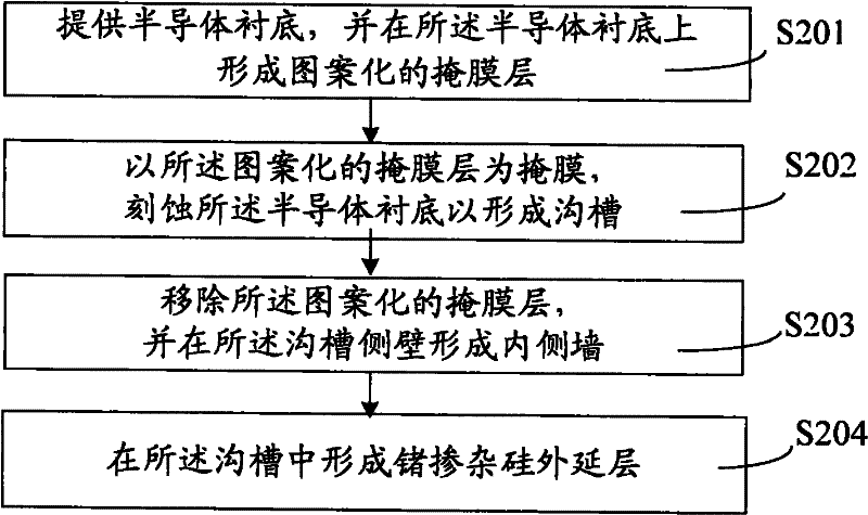
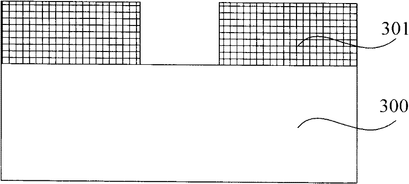
[0031] Such as figure 2 As shown, the present invention provides a method for manufacturing a MOS transistor, which is completed by the steps shown in S201 to S204, combined below figure 2 The flow chart of the fabrication process of the MOS transistor and Figure 3A ~ 3E The schematic cross-sectional structural diagram of the manufacturing process of the MOS transistor is described in detail for the manufacturing method of the above-mentioned MOS transistor.

[0032] S201, providing a...


PUM


Abstract

The invention provides a manufacturing method for an MOS transistor. On one hand, charge mobility is increased by germanium-doped silicon epitaxy to inhibit hot carrier's effect; on the other hand, by an inner wall with a lower top, radial diffusion is inhibited in lightly doped source/drain (LDD) region after ion implantation and the depth of the lightly doped source/drain (LDD) extension region is controlled, which allows ultra-shallow junction shallower. Therefore longer effective channel is obtained, HCI effect is effectively inhibited, SCE and RSCE effects are significantly improved and breakdown effect and electric leakage caused by breakdown effect brought by shrunk device size are reduced, enabling the production of even shallower source/drain region junction in the ultra-shallow junction technology.

Description

technical field [0001] The invention relates to the field of semiconductor manufacturing, in particular to a method for manufacturing a MOS transistor. Background technique [0002] As the size of MOSFET devices continues to shrink, especially when entering the node of 65 nanometers and below, MOSFET devices highlight various adverse physical effects due to the extremely short channel, especially the short channel effect (SCE), which makes the device performance and reliability Sexual degradation, which limits the further reduction of feature size. Currently, an ultra-shallow junction structure (a doped junction with a junction depth below 100 nm, USJ) is usually used to improve the short-channel effect of the device. [0003] In the prior art, the low-energy lightly doped source / drain region (LDD) ion implantation is usually performed sequentially with the first ion and the second ion to form a lightly doped source / drain extension region (such as figure 1 101) to achieve ...

Claims


Application Information

Patent Timeline
Patent Type & Authority Applications(China)
IPC IPC(8): H01L21/336
CPCH01L29/7833H01L29/0653H01L29/1054
Inventor 赵猛
Owner SEMICON MFG INT (SHANGHAI) CORP
Why Eureka
Try Eureka