Use method for circulating comprehensive utilization device for blast furnace gas

A technology of blast furnace gas and blast furnace, which is applied in the field of blast furnace gas cycle comprehensive utilization device, can solve problems such as insufficient heat utilization, lower combustion temperature of combustion system, increase of gas, etc., to avoid early scrapping, increase of combustion temperature, and prolong service life Effect

Inactive Publication Date: 2012-10-03
BEIJING SHOUGANG INT ENG TECH
View PDF8 Cites 14 Cited by
  • Summary
  • Abstract
  • Description
  • Claims
  • Application Information

AI Technical Summary

Problems solved by technology

[0003] 1. Blast furnace gas purification adopts wet dedusting process technology, which reduces the effective temperature of blast furnace gas and increases the non-combustible component water vapor in the gas while dedusting, resulting in a decrease in the combustion temperature of the combustion system of the industrial furnace and an increase in combustion. The production cost of system operation, and the wet dedusting also needs to set up dedusting water treatment facilities, which increases the investment and operation costs
[0004] 2. The blast furnace gas that has undergone wet dedusting can only be used in the downstream process through a decompression device. The decompression device reduces the original pressure of the blast furnace gas from 0.15 to 0.25MPa to 0.015MPa, so that the original pressure of the blast furnace gas cannot be recycled. At the same time, noise up to 120dB(A) is generated during the decompression process, forming noise pollution
[0005] 3. The remaining blast furnace gas is sent to the boiler room of the power station for combustion to generate steam and then enters the steam turbine unit to generate electricity. Since the efficiency of the steam turbine can only reach about 30% at present, its work efficiency is not high, resulting in poor utilization of heat full

Method used


Image

  • Use method for circulating comprehensive utilization device for blast furnace gas

Examples


Embodiment 1

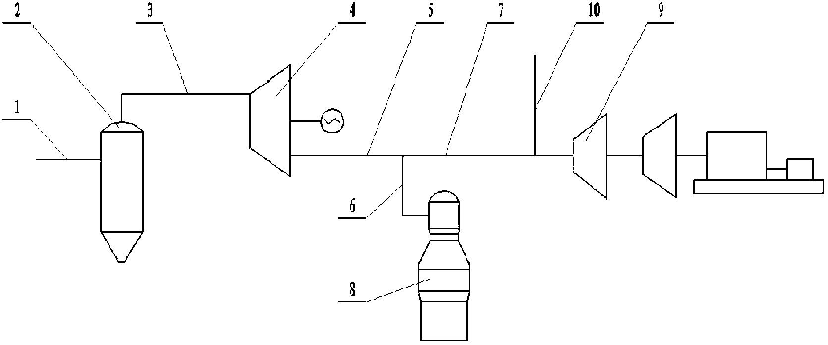
[0022] like figure 1 As shown, a blast furnace gas cycle comprehensive utilization device includes a dry bag type pulse dust removal device 2, a fully dry blast furnace gas residual pressure recovery device 4, a blast furnace hot blast stove device 8, a gas-steam combined cycle power generation device 9, and an original blast furnace gas Pipeline 1, high-pressure clean blast furnace gas pipeline 3, low-pressure blast furnace gas pipeline 5, blast furnace hot blast stove leading blast furnace gas pipeline 6, gas-steam combined cycle power generation device leading blast furnace gas pipeline 7, maintenance and exporting blast furnace gas pipeline 10. The specific process steps and parameters are:

[0023] 1) The blast furnace gas discharged from the top of the blast furnace enters the dry bag pulse dust removal device 2 from the lower part through the original blast furnace gas pipeline 1. The back blowing type of the dry bag pulse dust removal device 2 is pulse type, and it ado...


PUM


Abstract

A use method for a circulating comprehensive utilization device for blast furnace gas belongs to the technical field of utilization of blast furnace gas and comprises the following process steps that: the blast furnace gas exhausted by the top of a blast furnace enters a dry-method bag-type pulse dust removing device from the lower part of an original blast furnace gas pipeline for filtering; the filtered blast furnace gas enters a full-dry type blast furnace gas residual pressure recovering device for reducing the temperature and pressure through a high-pressure net blast furnace gas pipeline; the blast furnace gas subjected to temperature and pressure reduction is inducted out by a low-pressure blast furnace gas pipeline; part of blast furnace gas is induced into the blast furnace gas pipeline through a blast furnace hot blast stove and enters a blast furnace hot blast stove device to finish a heating process; and residual part of blast furnace gas is inducted into the blast furnace gas pipeline through a gas-steam joint power generation device and enters the gas-steam joint circulating power generation device for recovering residual heat and pressure. The use method has the advantages that dust in the blast furnace gas is effectively removed; original pressure energy and heat energy of the blast furnace gas are recovered, the energy is saved, the consumption is reduced and high-efficiency comprehensive utilization of the blast furnace gas is realized.

Description

technical field [0001] The invention belongs to the technical field of blast furnace gas utilization. In particular, it relates to a method for using a blast furnace gas cycle comprehensive utilization device. Background technique [0002] While the blast furnace of a steel plant produces molten iron products, it also produces a large amount of by-product blast furnace gas. This part of the gas contains combustible gases such as CO and particles such as dust. The gas temperature is 150-250 °C and the gas pressure is 0.15- Within the range of 0.25MPa, the blast furnace gas can be transported to the industrial kiln of the iron and steel plant after purification and used as gas fuel. In the past, the blast furnace gas was exported from the ascending pipe and descending pipe at the top of the blast furnace, passed through the wet dust removal device and the blast furnace gas pressure regulating valve group, and then used as purified process fuel gas, and part of it was sent to ...

Claims


Application Information

Patent Timeline
Patent Type & Authority Applications(China)
IPC IPC(8): C21B5/06
CPCY02P10/25
Inventor 张福明韩渝京侯健陶有志
Owner BEIJING SHOUGANG INT ENG TECH
Why Eureka
Try Eureka