Resistance pit annealing furnace

An annealing furnace and resistance technology, applied in heat treatment equipment, heat treatment process control, manufacturing tools, etc., can solve the problems of large one-time investment and complex design, and achieve the effect of reducing investment, saving costs, and simple overall structure design.

Inactive Publication Date: 2012-10-03
河北二十冶建设有限公司
View PDF2 Cites 6 Cited by
  • Summary
  • Abstract
  • Description
  • Claims
  • Application Information

AI Technical Summary

Problems solved by technology

[0003] The purpose of the present invention is to provide a resistance pit annealing furnace to solve the problem of complex design and large one-time investment of the existing pit annealing furnace

Method used


Image

  • Resistance pit annealing furnace
  • Resistance pit annealing furnace
  • Resistance pit annealing furnace

Examples


Embodiment Construction

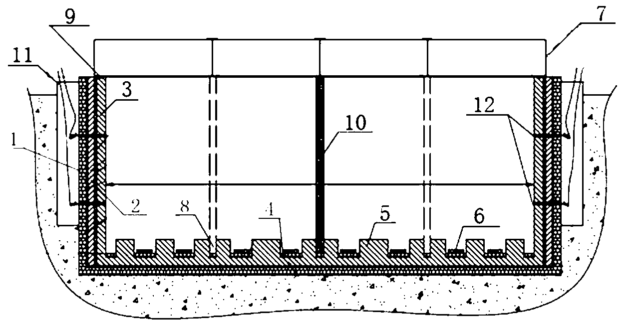
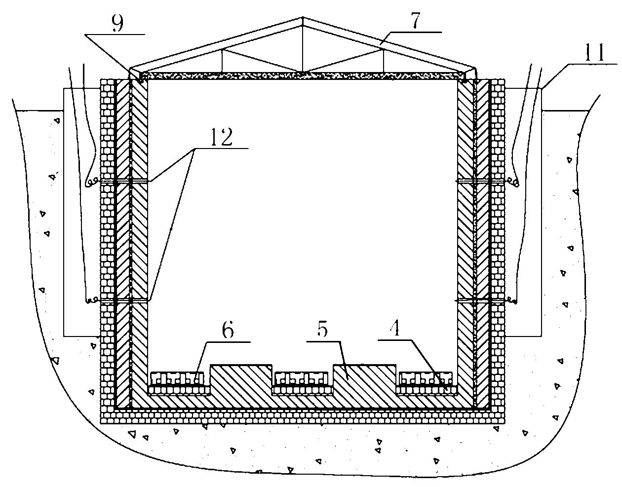
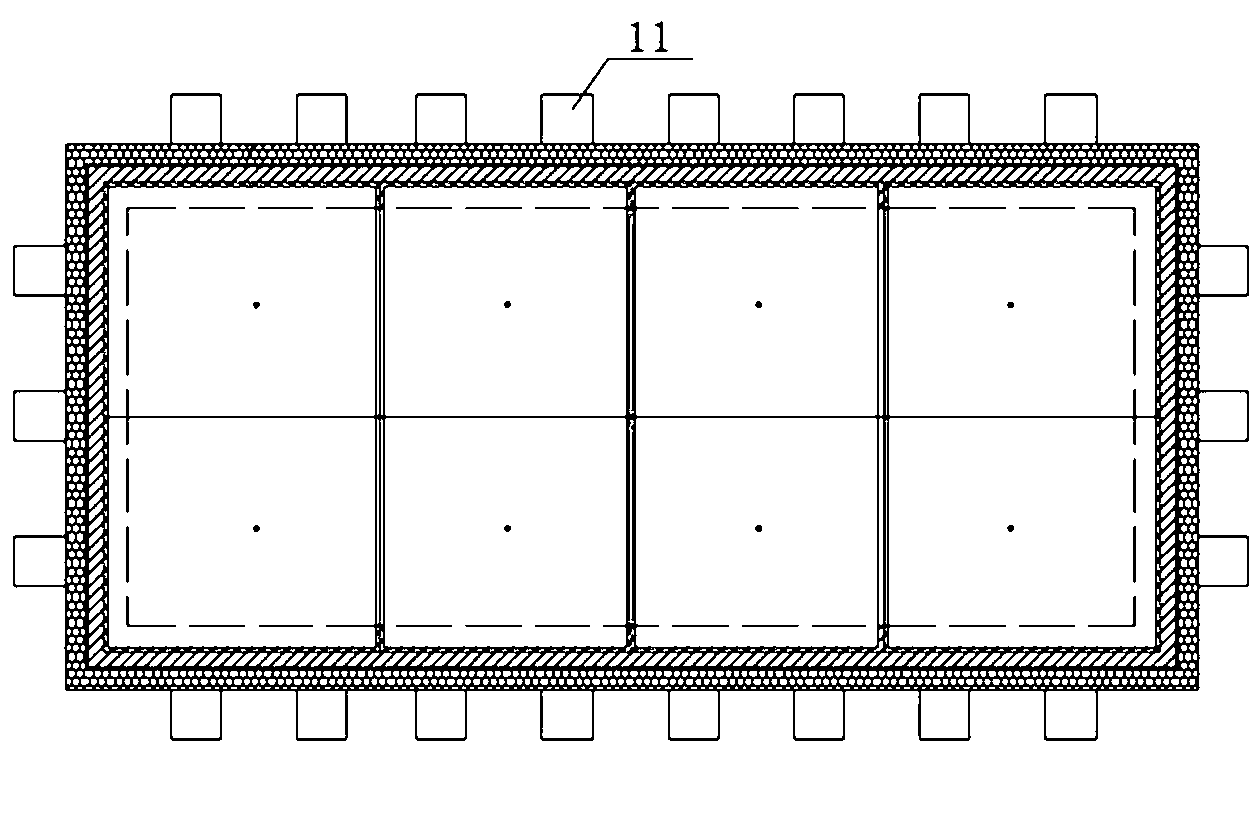
[0021] Such as Figure 1~Figure 4 As shown, the furnace body shown in the figure is in the shape of a cuboid, of course, it can also be in the shape of a cube. The furnace body is mainly buried in the pit under the ground. The furnace wall and furnace bottom adopt integral pouring design. The furnace wall includes: brick wall 1→cement mortar plastering layer (or plastering layer)→waterproof layer from outside to inside →Reinforced concrete furnace wall 2→Refractory fiberboard insulation layer→Heat-resistant reinforced concrete furnace wall 3. The upper edge of the furnace wall may be properly higher than the upper edge of the pit by 500-600mm. The outermost brick wall 1 of the furnace wall is designed to be 240mm thick. The inner wall of the brick wall 1 is plastered with cement mortar and then covered with 4mm thick SBS polyester tire waterproof membrane for two layers; the thickness of the reinforced concrete furnace wall 2 is 200mm. Two layers of 20mm thick refractory fib...


PUM

PropertyMeasurementUnit
thicknessaaaaaaaaaa

Abstract

The invention provides a resistance pit annealing furnace, which comprises a furnace body and a furnace cover, wherein the furnace body is embedded in a pit; the furnace cover covers on the top opening of the furnace body; buttresses are spread all over on the bottom face of the interior of the furnace body; an electric heating plate is arranged on a furnace bottom between each two buttresses; the furnace wall of the furnace body is provided with a plurality of temperature detectors; the electric heating plates and the temperature detectors are respectively and electrically connected onto a controller arranged outside the pit; a plurality of side walls for conducting wires and/or data lines to pass through are arranged between the outer wall of the furnace body and the wall of the pit; the wall of the furnace body consists of a brick wall, a plaster layer, a waterproof layer, a reinforced concrete furnace wall, a flame-retardant fiber board thermal insulation layer and a heat-resistance reinforced refractory castable furnace wall; and the furnace bottom of the furnace body consists of the brick wall, the plaster layer and the waterproof layer. According to the resistance pit annealing furnace provided by the invention, the furnace body is embedded in the pit, and the furnace bottom and the furnace wall can be integrally poured, so that the integral structure is simple in design; and the furnace bottom and the furnace wall respectively consist of the brick wall, the plaster layer and the waterproof layer, so that the cost can be saved, and the investment can be reduced.

Description

technical field [0001] The invention relates to an annealing device, in particular to a resistance pit type annealing furnace. Background technique [0002] After the welding parts, forgings, castings and other workpieces are processed, there are residual internal stresses in the workpieces. In order to improve the stability of the workpiece and prevent deformation and cracking, the workpiece must be subjected to stress relief annealing heat treatment, and the annealing process temperature is required to be below 700 °C. Initially, the company's annealing process was carried out in the gas-fired annealing furnace at the bottom of the car, but the construction cost of the gas-fired annealing furnace at the bottom of the car was high, and it was limited by the lifting height of the existing production plant site and lifting equipment, so the scope of use was narrow. At present, some domestic manufacturers have begun to use pit-type annealing furnaces to anneal and heat-treat ...

Claims


Application Information

Patent Timeline
Patent Type & Authority Applications(China)
IPC IPC(8): C21D1/30C21D1/40C21D11/00
Inventor 刘丹玉
Owner 河北二十冶建设有限公司
Why Eureka
Try Eureka