Micro-channel structure of heat exchanger

A micro-channel structure, heat exchanger technology, applied in the direction of heat exchanger type, indirect heat exchanger, heat exchange equipment, etc., can solve the problems of reduced fluid flow resistance, lack of induced condensation or evaporation phase change, etc. Enhanced thermal capacity, beneficial to phase change heat transfer, and enhanced heat transfer effect

Inactive Publication Date: 2012-10-03
浙江微智源能源技术有限公司 +1
View PDF8 Cites 18 Cited by
  • Summary
  • Abstract
  • Description
  • Claims
  • Application Information

AI Technical Summary

Problems solved by technology

Compared with straight channels, such microchannels can increase the forced convective heat transfer coefficient and reduce the pressure loss of the fluid. However, due to the lack of microstructures that catalyze condensation or evaporation phase transitions, the heat transfer performance of such structures still needs to be improved. The resistance to fluid flow needs to be further reduced

Method used


Image

  • Micro-channel structure of heat exchanger
  • Micro-channel structure of heat exchanger
  • Micro-channel structure of heat exchanger

Examples


Embodiment 1

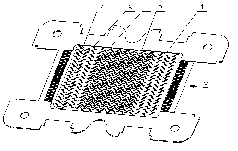
[0032] figure 1 It is a new type of microchannel structure patented by the present invention, wherein the microchannel is formed between multi-layer stacked heat exchange plates 1, and a plurality of fin units 2 are formed on the heat exchange plate 1, and the fin units 2 Fin unit groups 7 are evenly arranged in the direction perpendicular to the fluid flow, and a plurality of fin unit groups 7 are arranged alternately at intervals along the fluid flow direction; the rear end of the fin unit 2 on the upstream side It is arranged in the middle of two adjacent fin units 2 on the downstream side. The intermediate position in the present invention refers to any position between two adjacent fin units 2 on the downstream side, which not only includes the rear end of the fin unit 2 on the upstream side protruding into the adjacent fin unit 2 on the downstream side. The interior between the fin units 2 also includes the exterior between the adjacent fin units 2 on the downstream si...

Embodiment 2

[0041] Figure 4 and Figure 5 It is another microchannel structure of the present invention, which is basically the same as the microchannel structure in Example 1, the difference lies in the shape of the fin unit.

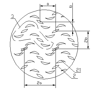
[0042] The outer contour of the fin unit 2 is linear. Specifically, in this embodiment, the fin unit 2 is composed of three parallelogram fins 21, and the obtuse angle sides of the parallelogram 21 are Arc transition. The microchannel with such a structure avoids the eddy current formed by continuous curves, thereby reducing the resistance loss of flow. The angle α between the fin unit 2 and the fluid flow direction is 45 0 .

[0043] Among them, such as Figure 4 As shown, the distance a between the two fin units 2 in the fluid flow direction is 1 mm, and the distance b perpendicular to the fluid flow direction is 2 mm; the fluid flow between adjacent pairs of fin units 3 The spacing in the direction is 3 mm, and the spacing between adjacent pairs of fin u...

Embodiment 3

[0047] The microchannel structure of this embodiment is basically the same as that of Embodiment 2, the difference lies in the arrangement position and size parameters of the fins.

[0048] Wherein, the angle α between the fin unit 2 and the fluid flow direction is 55° 0 . The distance a between the two fin units 2 in the direction of fluid flow is 1.5 mm, and the distance b perpendicular to the direction of fluid flow is 1.5 mm; between adjacent pairs of fin units 3 in the direction of fluid flow The spacing above is 3 mm, and the spacing between adjacent pairs of fin units 3 perpendicular to the fluid flow direction is 4 mm.

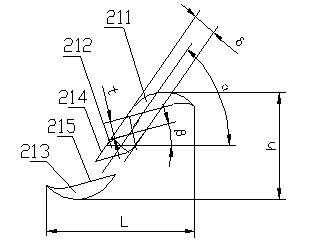
[0049] Such as Figure 5 As shown, the length L of the fin unit 2 along the direction of fluid flow is 2 mm, the width h perpendicular to the direction of fluid flow is 1 mm, and the thickness δ of the fin is 0.25 mm.

[0050] The distance t between the splitter edges 214 adjacent to the fins 21 is 0.05 mm; the included angle β between the splitter ...


PUM


Abstract

The invention discloses a micro-channel structure of a heat exchanger, and a micro-channel is respectively formed among multiple layers of laminated heat exchanging plates (1), each heat exchanging plate (1) is provided with a plurality of fin units (2), the fin units (2) are uniformly distributed along the direction which is vertical to the flowing direction of fluid to form a fin unit group (7), and a plurality of fin unit groups (7) are alternately arranged at intervals along the flowing direction of the fluid; the rear ends of the fin units (2) at the upstream side are arranged in the middle position of every two adjacent fin units (2) at the downstream side; each fin unit (2) consists of at least two sections of fins (21), and the two adjacent fins (21) are separated from each other for a given distance; and the micro-channel is formed by fluid channels respectively between two adjacent fin units (2) and between two adjacent fins (21). Due to the adoption of the micro-channel structure of the heat exchanger, under the situation that the small flowing resistance force is kept, the forced convection heat conduction coefficient is increased, and the heat exchanging capacity of the heat exchanger is enhanced.

Description

technical field [0001] The invention relates to a microchannel structure of a heat exchanger, in particular to a streamlined microchannel structure. Background technique [0002] In the current field of heat exchangers, microchannel heat exchangers are a new direction for research, development and application of heat exchangers due to their small size, light weight, and high compactness. [0003] Existing microchannel heat exchangers used in heat pump systems are almost all realized with flat aluminum tube profiles plus inlets and outlets for refrigerant and working fluid, which are limited to heat exchange between refrigerant and air. bifurcated heat exchanger. For example, a microchannel heat exchanger disclosed in Chinese patent document CN102095285A is the above-mentioned bifurcated heat exchanger. Since the heat exchange flat tube is an aluminum tube profile, the size of the profile is a fixed value. There are restrictions on the selection of the hydraulic diameter o...

Claims


Application Information

Patent Timeline
Patent Type & Authority Applications(China)
IPC IPC(8): F28F3/04F28D9/02
Inventor 石景祯王凱建
Owner 浙江微智源能源技术有限公司
Why Eureka
Try Eureka