

Infrared radiation illumination measuring instrument and method using measuring instrument to measuring infrared radiation illumination
An infrared radiation and illuminance measurement technology, applied in the optical field, can solve the problems of large size, inconvenient to carry, large error, etc., to achieve the effect of ensuring accuracy and stability, solving the problem of portability, and reasonable calibration results
- Summary
- Abstract
- Description
- Claims
- Application Information
AI Technical Summary
Problems solved by technology
Method used
Image

Examples
specific Embodiment approach 1
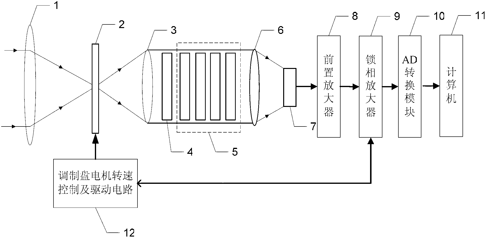
[0027] Specific implementation mode one: the following combination figure 1 Describe the present embodiment, the infrared radiation illuminance measuring instrument described in the present embodiment, it comprises main objective lens 1, reticle 2, the first relay lens 3, optical filter 4, attenuation sheet group 5, the second relay lens 6, Photodetector 7, preamplifier 8, lock-in amplifier 9, AD conversion module 10, computer 11 and dial motor speed control and drive circuit 12,
[0028] The parallel light beam is incident on the main objective lens 1, the main objective lens 1 outputs a converging beam and enters the modulation disc 2, the modulation disc 2 outputs a modulated beam and enters the first relay lens 3, and the relay lens 3 outputs a parallel beam and enters the optical filter 4 , the transmitted light beam output by the optical filter 4 is incident on the second relay lens 6 through the parallel attenuated light beam after the attenuating sheet group 5, and the...
specific Embodiment approach 2
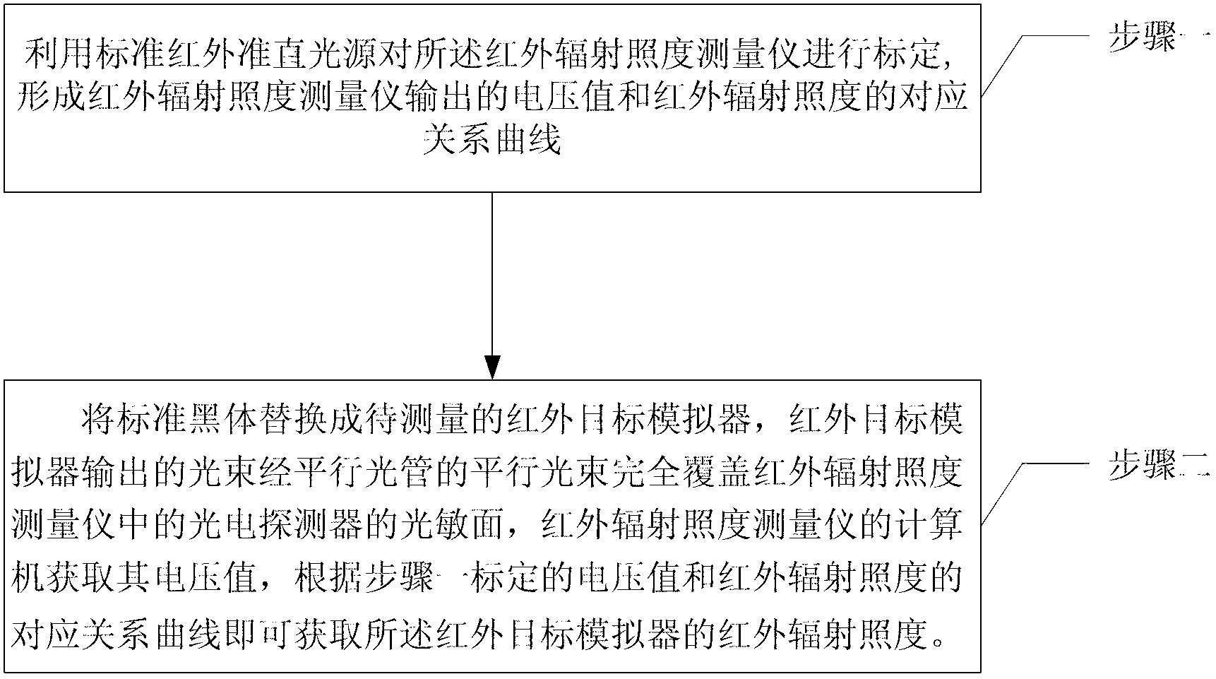
[0035] Specific implementation mode two: the following combination Figure 1 to Figure 3 To illustrate this embodiment, the method for measuring infrared illuminance by using the infrared illuminance measuring instrument described in Embodiment 1 includes the following steps:
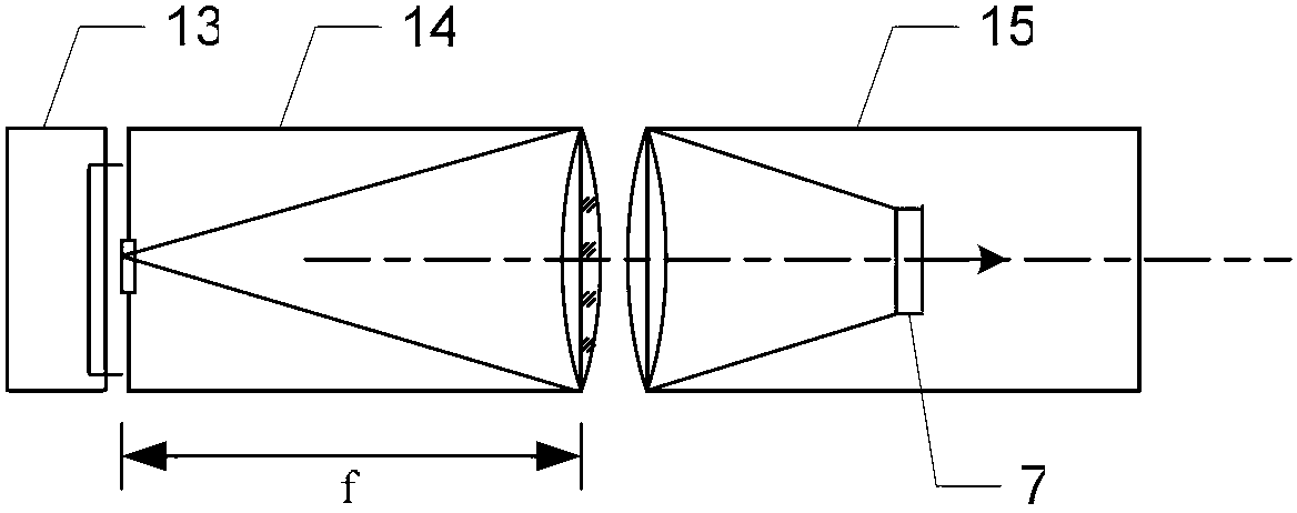
[0036] Step 1, using a standard infrared collimated light source to calibrate the infrared radiation illuminance measuring instrument 15:
[0037] The infrared collimated light source is realized by a standard blackbody 13, the output beam of the standard blackbody 13 passes through the collimator 14, and the output parallel beam is incident on the infrared illuminance measuring instrument 15, and the standard blackbody 13, the collimator 14 and the infrared illuminance measuring instrument are adjusted 15, so as to satisfy the parallel light beam incident to the infrared illuminance measuring instrument 15 and completely cover the photosensitive surface of the photodetector 7 in the infrared irradiance...
PUM
 Abstract
Description
Claims
Application Information