
Terminal forming machine and method for pole piece of lithium battery

A molding machine, lithium battery technology, applied in the direction of battery electrodes, circuits, electrical components, etc., can solve the problems affecting the charging and discharging quality of the battery, the welding of the tabs is not strong, and the resistance of the welding place is large, and the cutting pattern can be set flexibly and follow-up. The effect of convenient process and high cutting efficiency

Active Publication Date: 2012-10-03
GEESUN AUTOMATION TECH
View PDF3 Cites 27 Cited by
  • Summary
  • Abstract
  • Description
  • Claims
  • Application Information

AI Technical Summary

Problems solved by technology

[0002] In the manufacturing process of lithium-ion batteries (especially large-capacity lithium-ion batteries), there are usually two ways to make pole pieces: one way is to use ultrasonic welding technology to weld the pole piece before the battery core is wound. The independent nickel strip lugs are welded on the pole pieces. In this way, the lugs and pole pieces are connected by solder joints. On the one hand, the resistance of the welding place is relatively large, which affects the charging and discharging quality of the battery. On the other hand, if the quality of the ultrasonic welding process is not good Stable or unbalanced speed of pole piece incoming material and nickel belt material, which may easily cause problems such as poor welding of tabs, slow production speed, and low pass rate
The second method is to cut and form tabs on the pole pieces by die cutting and metal die cutting before the Z-shaped laminations are used to make batteries. This method avoids the high resistance of the connection between the tabs and the pole pieces. However, die cutting is likely to cause quality problems such as large burrs and easy powder loss, resulting in low pass rate. At the same time, this method also has problems such as slow production speed and short die life.
[0003] It can be seen that the existing pole piece production methods and equipment need to be improved urgently

Method used


Image

  • Terminal forming machine and method for pole piece of lithium battery
  • Terminal forming machine and method for pole piece of lithium battery
  • Terminal forming machine and method for pole piece of lithium battery

Examples


Embodiment Construction

[0024] The present invention will be further described in detail below through specific embodiments in conjunction with the accompanying drawings.

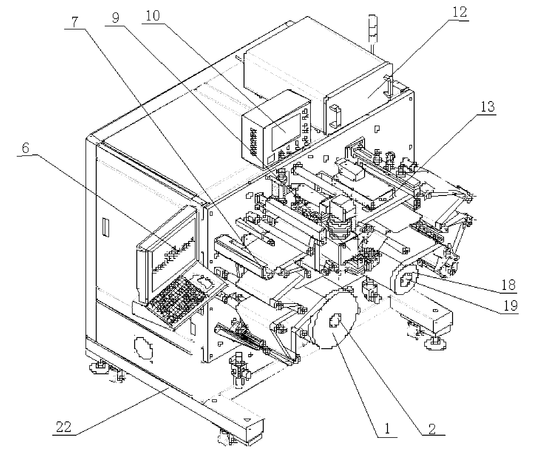
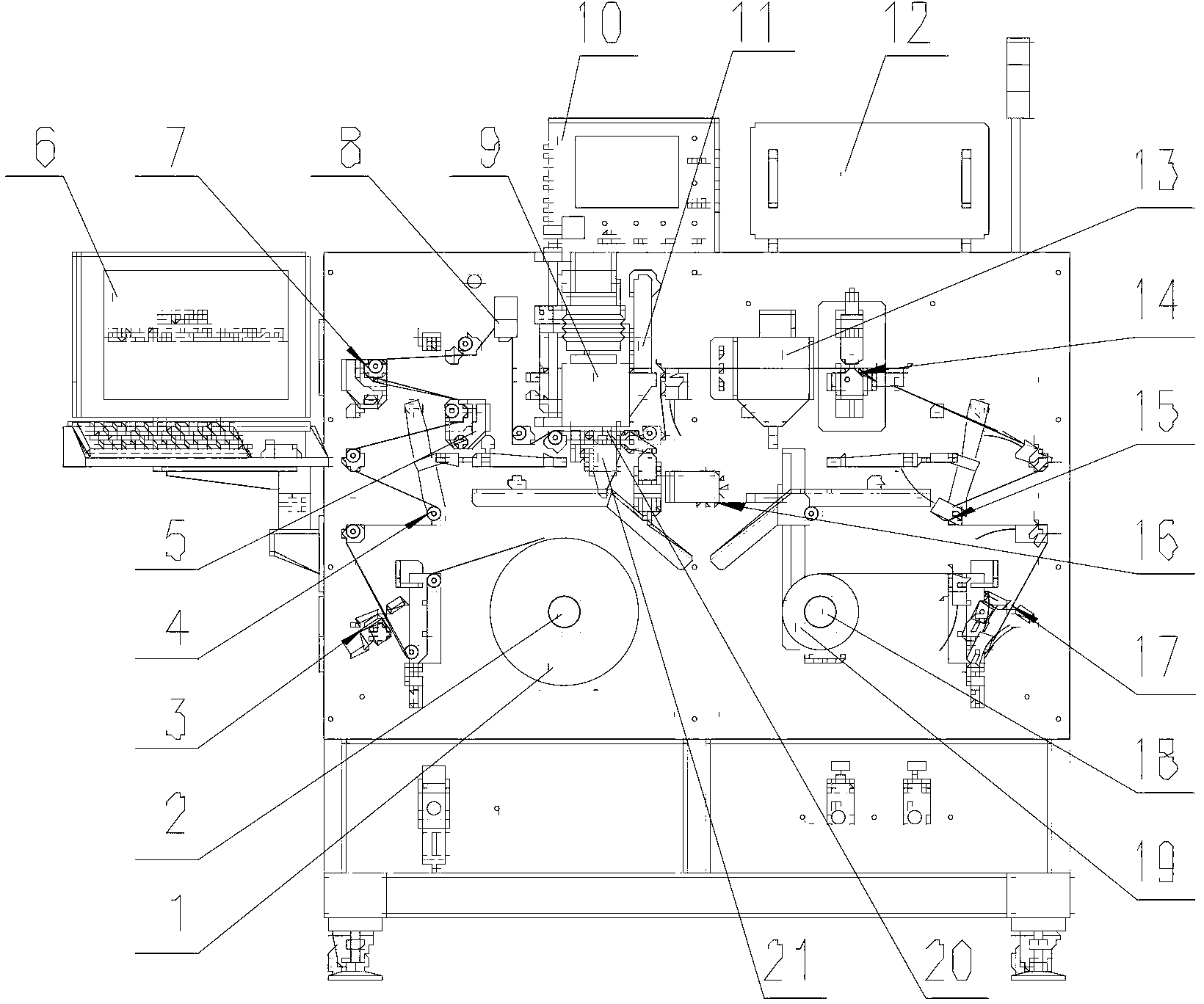
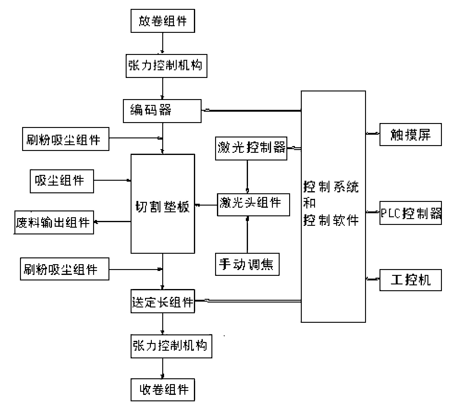
[0025] In the embodiment of the present application, the ear forming machine for the lithium battery pole piece uses a laser to cut the lithium ion battery pole piece to form the tab. Under the control of the control system, the laser head assembly uses the laser head to continuously cut the pole pieces on the cutting backing plate according to the preset cutting pattern or cutting parameters to form tabs, and finally transports the cut pole pieces to the winding assembly Form rolls.

[0026] Please refer to figure 1 and figure 2 , the ear forming machine for lithium battery pole pieces in this embodiment mainly includes a frame 22, and an unwinding assembly 2 installed on the frame 22, two tension control mechanisms, three dusting and dusting assemblies, and a cutting backing plate 20 , laser cutting head 9, sending fixed len...


PUM


Abstract

The invention discloses a terminal forming machine and method for a pole piece of a lithium battery. The terminal forming machine comprises an unwinding component (2), a cutting base plate (20), a laser cutting head (9), a winding component (18) and a control system, wherein the cutting base plate (20) is placed on a pole piece motion path between the unwinding component (2) and the winding component (18), the laser cutting head (9) is arranged over the cutting base plate (20), and the control system is connected with the unwinding component (2), the laser cutting head (9) and the winding component (18) through signals. The terminal forming machine and method have the advantages that the pole producing process quality is remarkably improved, the consistency of a battery cell is guaranteed, the pole producing efficiency is improved, and subsequent handling of the pole producing process is facilitated.

Description

technical field [0001] The present application relates to the field of batteries, in particular to a tab forming machine and a tab forming method for lithium battery pole pieces. Background technique [0002] In the manufacturing process of lithium-ion batteries (especially large-capacity lithium-ion batteries), there are usually two ways to make pole pieces: one way is to use ultrasonic welding technology to weld the pole piece before the battery core is wound. The independent nickel strip lugs are welded on the pole pieces. In this way, the lugs and pole pieces are connected by solder joints. On the one hand, the resistance of the welding place is relatively large, which affects the charging and discharging quality of the battery. On the other hand, if the quality of the ultrasonic welding process is not good Stable or unbalanced speeds of pole piece incoming material and nickel belt material may easily cause problems such as poor welding of tabs, slow production speed, an...

Claims


Application Information

Patent Timeline
IPC IPC(8): H01M4/139
CPCY02E60/122Y02E60/10
Inventor 陈强阳如坤
Owner GEESUN AUTOMATION TECH
Learn More