Control method of drive system of salient pole type permanent magnet synchronous motor

A permanent magnet synchronous motor and drive system technology, applied in motor generator control, electronic commutation motor control, control system, etc., can solve the control limitations of permanent magnet synchronous motor drive system, time-consuming and laborious experimental equipment requirements, and can not characterize the motor. Cross-coupling effects, etc.

Active Publication Date: 2012-10-03
HEFEI UNIV OF TECH
View PDF2 Cites 17 Cited by
  • Summary
  • Abstract
  • Description
  • Claims
  • Application Information

AI Technical Summary

Problems solved by technology

However, when designing the core control algorithm of the existing permanent magnet synchronous motor drive system, the motor inductance is selected as the motor system parameter to control the motor, and the motor inductance only contains the information of the magnetic circuit saturation and cross saturation degree of the motor at different operating points , cannot characterize motor cross-coupling effects
[0006] In order to simplify the calculation and facilitate real-time control, it is usually assumed that the inductance of the motor is fixed, or only the influence of magnetic circuit saturatio

Method used


Image

  • Control method of drive system of salient pole type permanent magnet synchronous motor
  • Control method of drive system of salient pole type permanent magnet synchronous motor
  • Control method of drive system of salient pole type permanent magnet synchronous motor

Examples


Embodiment Construction

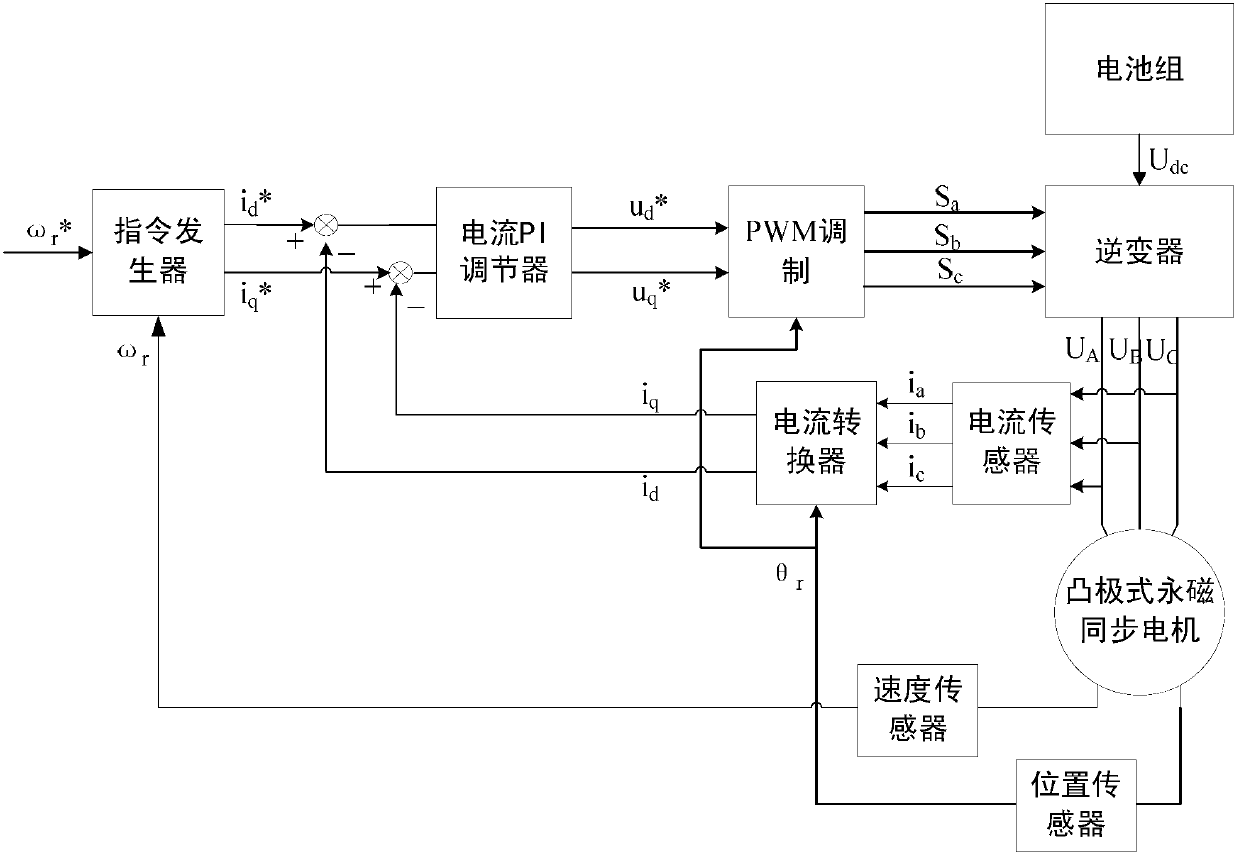
[0080] In this example, if figure 2 As shown, the composition of the salient pole permanent magnet synchronous motor drive system includes: battery pack, current PI regulator, PWM modulation module, inverter, salient pole permanent magnet synchronous motor, current sensor, speed sensor, position sensor, current converters and command generators;

[0081] The battery pack is used to provide DC power for inversion to the salient pole permanent magnet synchronous motor;

[0082] The current PI regulator is used to convert the current control signal output by the command generator into a voltage control signal;

[0083] The PWM modulation module is used to convert the voltage control signal into an inverter control signal;

[0084] The inverter adopts a three-phase full-bridge voltage type, and uses the received inverter control signal to convert the DC power provided by the battery pack into AC power to drive the salient pole permanent magnet synchronous motor to work;

[0085]...


PUM


Abstract

The invention discloses a control method of a drive system of a salient pole type permanent magnet synchronous motor. The control method is characterized by comprising the steps of: acquiring a d-shaft current instruction fitting expression and a q-shaft current instruction computation expression of an instruction generator by adopting a motor electric magnetic field finite element analysis method according to detected stator a-phase current ia, stator b-phase current ib, stator c-phase current ic, rotor actual position angle theta r, and actual speed omega r, producing a d-shaft stator current instruction id<*> and a q-shaft stator current instruction iq<*> by the instruction generator, acquiring a stator d-shaft voltage instruction ud<*> and a stator q-shaft voltage instruction uq<*> via a current PI (Proportional-Integral) regulator, obtaining three control signals including Sa, Sb and Sc of an inerter by a PWM (Pulse Width Modulation) module according to the acquired instructions, converting voltage udc supplied by a battery pack into control voltages UA, UB and UC of the salient pole type permanent magnet synchronous motor via the inverter by using the three control signals Sa, Sb and Sc, thereby realizing the control of the permanent magnet synchronous motor. The control method disclosed by the invention can be used for effectively increasing the torque output of the permanent magnet synchronous motor under the same current, thereby increasing the control performance of the drive system of the permanent magnet synchronous motor.

Description

technical field [0001] The invention relates to a motor control system, in particular to a control method for a salient-pole permanent magnet synchronous motor drive system. Background technique [0002] The salient pole permanent magnet synchronous motor has the advantages of high efficiency, high power density, small torque ripple, fast dynamic response, wide speed range, etc., and is currently widely used in the field of electric vehicle electric drive systems. [0003] Affected by the characteristics of permanent magnet materials and the operating conditions of the salient pole permanent magnet synchronous motor drive system, the d-axis inductance parameters and q-axis inductance parameters of the permanent magnet synchronous motor generally do not remain constant in the entire operating area, especially in the permanent magnet synchronous motor. When the synchronous motor drive system operates under certain working conditions, it is prone to magnetic circuit saturation,...

Claims


Application Information

Patent Timeline
IPC IPC(8): H02P21/14H02P21/12H02P21/16
Inventor 李红梅李峥
Owner HEFEI UNIV OF TECH
Why Eureka
Try Eureka