Method for measuring radius of curvature of spherical surface

A technology of radius of curvature and spherical surface to be measured, applied in measurement devices, instruments, optical devices, etc., can solve the problems of complex spherical curvature radius detection methods, low detection cost, inability to detect multi-layer spherical curvature radius, etc., and achieve an important technology Value and economic value, reduced production process, effect of simple structure

Inactive Publication Date: 2012-10-17
深圳市鼎鑫盛光学科技有限公司
View PDF3 Cites 7 Cited by
  • Summary
  • Abstract
  • Description
  • Claims
  • Application Information

AI Technical Summary

Problems solved by technology

[0004]Technical problem: The purpose of this invention is to: propose a method for measuring the radius of curvature of a spherical surface, which is used to solve the problem of complex and multi-layered spherical curvature detection methods in the existing spherical curvature radius Radius can not be detected and other problems, so that the detection cost is low and detection is easy

Method used


Image

  • Method for measuring radius of curvature of spherical surface
  • Method for measuring radius of curvature of spherical surface

Examples


Embodiment 1

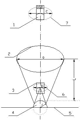
[0025] Detect the radius of curvature of a small droplet. Such as figure 1 , the size of the droplet is on the order of mm, and the ring light source is reflected by the surface of the droplet to form a reduced image, which is enlarged by the microscopic system, and then captured by the CCD camera as a picture and sent to the computer for storage through the data line. According to the above formulas (2) and (3), we can get , substituting into formula (1) to get . If the small water drop in the air environment on the plane is regarded as a lens, the focal length of the liquid lens can be calculated as: .

Embodiment 2

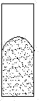
[0027] Detects the focal length of the liquid lens. Such as figure 2 , is a schematic diagram of the structure of a two-liquid lens. In the figure, the meniscus-shaped contact surface of two immiscible liquids, oil and water, is a liquid lens. There are two planes and one curved surface in the figure. When using this method to measure the radius of curvature of the curved surface, the standard object will form three images through the three surfaces, but the imaging size of the curved surface is small. Use a microscope system with a slightly larger objective lens to observe and record , which can effectively exclude the other two images from the field of view. This case can be used for real-time dynamic measurement of focal length, for example, the voltage-applied zoom curve of a liquid zoom lens based on the electrowetting effect can be measured. At this time, since the refractive index of oil and water are relatively close, the reflected light is not obvious, and a ring-s...


PUM


Abstract

The invention relates to a method for measuring the radius of curvature of a spherical surface. According to the method, a reference substance (2) of which the size is a is coaxial with a microscope objective (3), and the distance between the reference substance (2) and the vertex of a measured spherical surface (4) is L, wherein L can be changed independently in the axial direction; the reference substance (2) is reflected by the measured spherical surface on an object carrying platform (5) to form an image (6) of which the size is b, the image (6) is subjected to microscopic amplification by a microscope system to form an image (7) of which the size is c, and the image (7) is acquired by a charge coupled device (CCD) camera arranged on a microscope ocular lens (1) and is stored in a computer. The radius of curvature r of the measured spherical surface can be expressed by a function which contains the parameters of a, c and L, wherein a and L are measured directly, and c is measured by utilizing computer software, so that the radius of curvature of the measured spherical surface r can be measured. The reference substances are annular cross hairs or annular illuminants preferably, and can be equipped with multiple groups according to requirements. Preferably, the magnifying power of the microscope objective is continuously adjustable.

Description

technical field [0001] The invention relates to a method for measuring the radius of curvature of a spherical surface, belonging to the technical field of photoelectric detection. Background technique [0002] The measurement of spherical curvature radius is of great significance, and it is an important parameter in the process of optical lens processing, inspection and assembly. Fast and accurate measurement has always been a difficult point in the field of optics. Contact measurement is easy to implement, but the measurement speed is slow and will cause damage to the curved surface, and it cannot measure liquid-like curved surfaces; non-contact optical methods such as interferometry are more complicated, require high system adjustment, and are susceptible to environmental interference Influence. The photoelectric autocollimator adopts the aiming method of the electronic eyepiece, but requires a high-precision sensor, and the cost is relatively high. [0003] The purpose ...

Claims


Application Information

Patent Timeline
IPC IPC(8): G01B11/255
Inventor 徐荣青陈陶常春耘梁忠诚
Owner 深圳市鼎鑫盛光学科技有限公司
Why Eureka
Try Eureka