Device for cutting the human cornea

A technology of cornea and equipment, which is applied in the field of preparation of LASIK flaps, can solve problems such as difficulty in accurately tracking eyes, retention, etc.

Active Publication Date: 2012-10-17
ALCON INC
View PDF5 Cites 10 Cited by
  • Summary
  • Abstract
  • Description
  • Claims
  • Application Information

AI Technical Summary

Problems solved by technology

It has been found that during LASIK treatment of the human eye, trapping of gases in the cornea during flap preparation can cause problems during ...

Method used


Image

  • Device for cutting the human cornea
  • Device for cutting the human cornea
  • Device for cutting the human cornea

Examples


Embodiment Construction

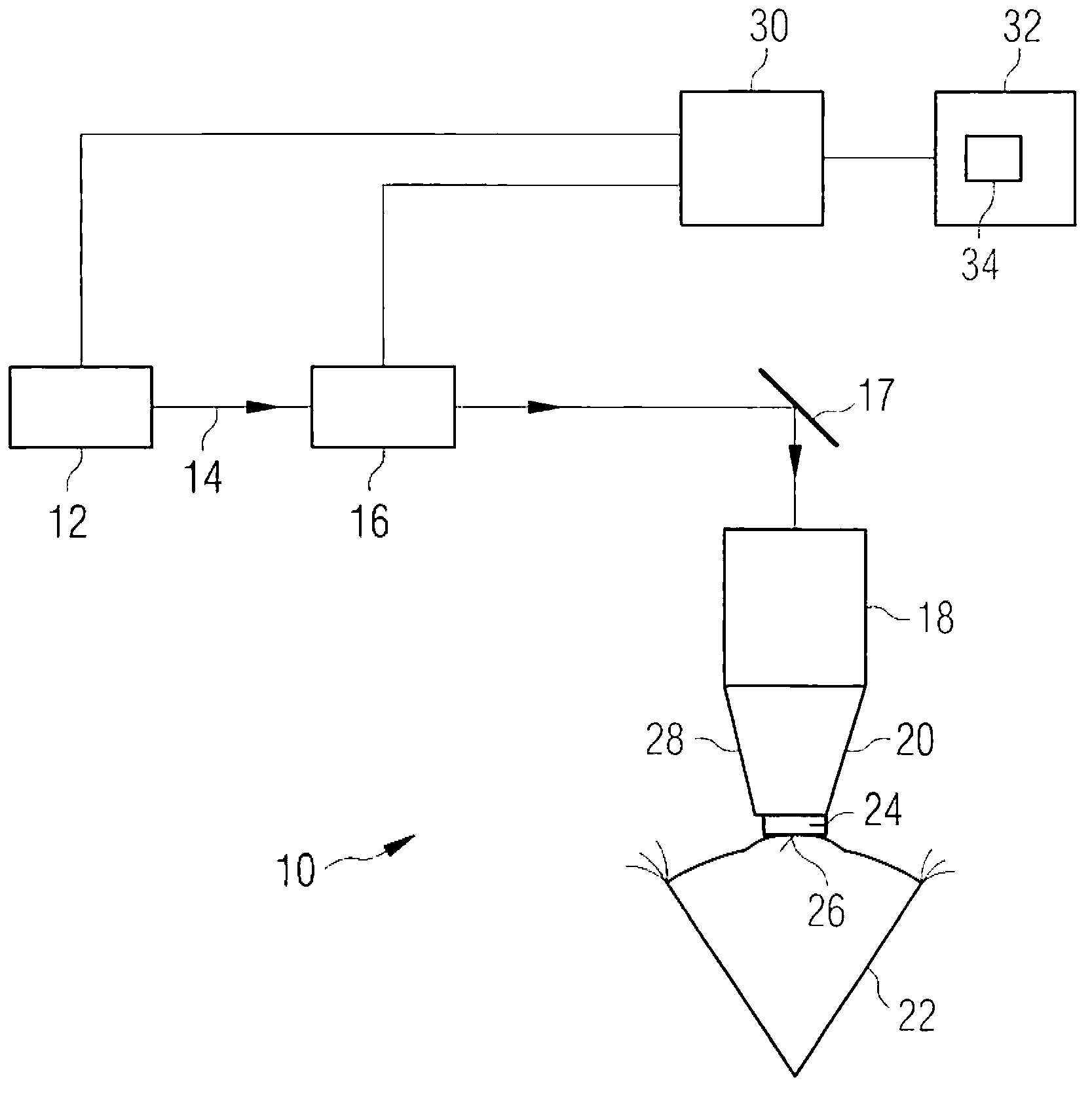
[0031] figure 1 The laser arrangement shown generally at 10 in includes a laser source 12 producing a laser beam 14 with a pulse duration in the femtosecond range. In the beam path of the laser beam 14, a number of components are arranged, including a scanner 16, here schematically represented as an integral functional block, and a fixed deflection mirror 17, as well as a focusing objective 18. The scanner 16 serves for lateral and longitudinal local control of the focus of the laser beam 14 . "Transverse" here means a direction at right angles to the direction of propagation of the laser beam 14, and "longitudinal" corresponds to the direction of propagation of the beam. In conventional notation, the transverse plane is referred to as the x-y plane and the longitudinal direction as the z-direction. For lateral deflection of the laser beam 14 (ie in the x-y plane), the scanner 16 may, for example, comprise a pair of amperometrically driven scanner mirrors tiltable about mutu...


PUM


Abstract

The invention relates to a device for cutting the human cornea using a focused, pulsed femtosecond laser beam comprises scanner components for adjusting the location of the beam focus, a control computer for controlling the scanner components, and a control program for the control computer. The control program contains instructions that are designed to cause a cutting pattern comprising a flap cut (38, 40) to be produced in the cornea when said instructions are executed by the control computer. According to the invention, the cutting pattern further comprises an auxiliary cut (50) that is connected to the flap cut and that leads preferably directly from the flap cut to the cornea surface. The auxiliary cut is advantageously produced before the flap cut and forms a purging channel through which gases that can develop while the flap cut is being cut can escape.

Description

technical field [0001] The present invention relates to the creation of incisions in the human cornea by focused laser radiation. In particular, the present invention relates to the preparation of LASIK flaps by such laser radiation. Background technique [0002] A common technique used to eliminate vision defects of the human eye, such as nearsightedness or farsightedness or astigmatism, is a technique known as LASIK. LASIK stands for laser in situ keratomileusis and designates a technique in which a small covering disc in the cornea is first cut away and folded aside so that the lower tissue region of the cornea is exposed . These exposed tissue regions are then treated ablatively by means of focused UV laser radiation, ie corneal material is removed according to an ablation profile determined individually for the patient. This small covering disc is commonly called a flap in expert circles, and instead of being completely separated from the rest of the cornea, it remai...

Claims


Application Information

Patent Timeline
IPC IPC(8): A61F9/01
CPCA61F2009/00897A61F9/00836A61F9/009A61F2009/00872A61F9/007A61F9/008
Inventor 克里斯托夫·德尼茨基马蒂亚斯·韦尔费尔
Owner ALCON INC
Why Eureka
Try Eureka