Magnetic pulse forming device and method of bimetal composite pipe

A bimetallic composite tube and magnetic pulse forming technology, which is applied in the field of magnetic pulse forming devices, can solve the problems of low bonding strength of composite bimetallic tubes, high danger of explosion composite method, complicated production process, etc., and the applicable occasions are not limited. , the production process is simple, the device structure is simple

Active Publication Date: 2012-10-24
HARBIN INST OF TECH
View PDF8 Cites 40 Cited by
  • Summary
  • Abstract
  • Description
  • Claims
  • Application Information

AI Technical Summary

Problems solved by technology

[0004] The purpose of the present invention is to provide a magnetic pulse forming device and method for bimetallic composite pipes to solve the problem of low bonding strength of composite bimetallic pip

Method used


Image

  • Magnetic pulse forming device and method of bimetal composite pipe
  • Magnetic pulse forming device and method of bimetal composite pipe
  • Magnetic pulse forming device and method of bimetal composite pipe

Examples


specific Embodiment approach 1

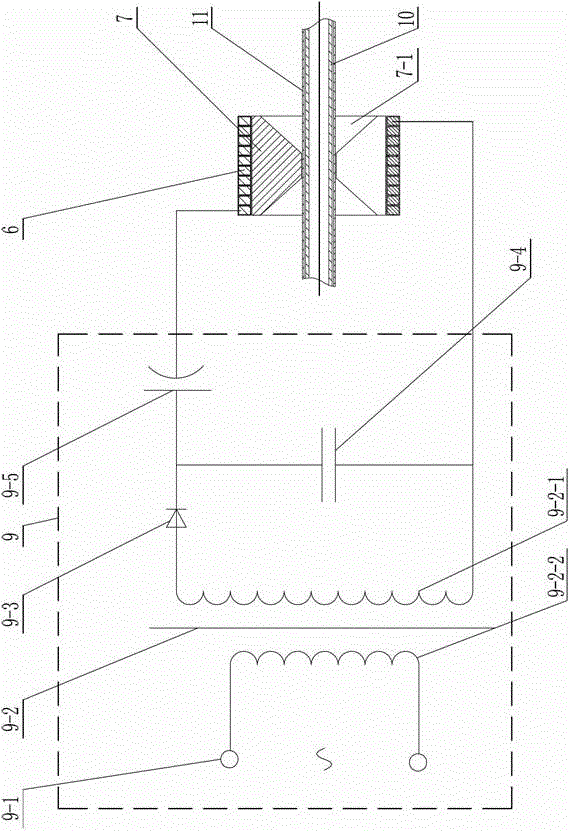
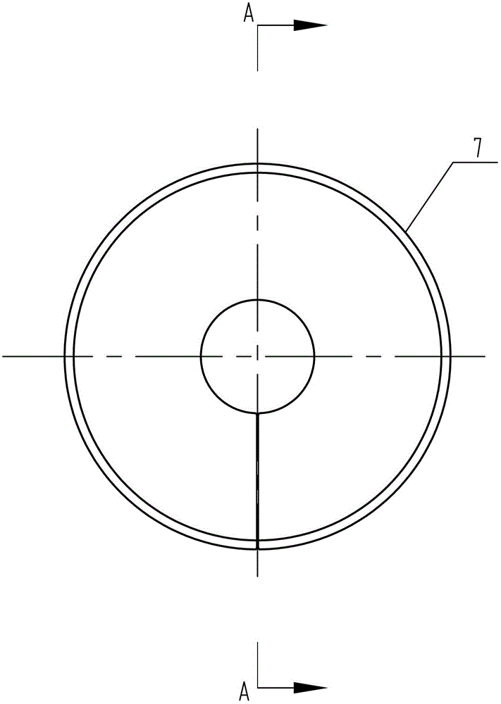
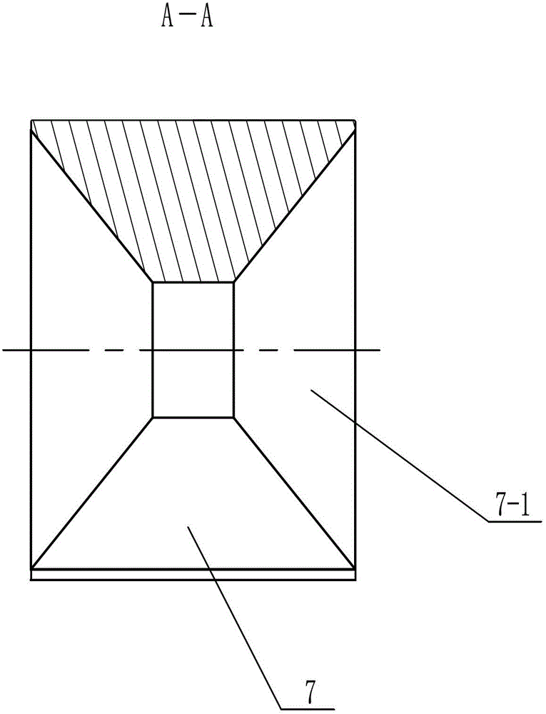
[0012] Specific implementation mode one: as Figure 1-Figure 5 As shown, the magnetic pulse forming device of the bimetallic composite pipe of the present embodiment includes a screw rod 1, a base fixing plate 2, a magnetic collector 7, a magnetic coil 6, a support frame 8, a magnetic pulse control circuit 9, two Tube blank clamping block 5 and two vise 4, the two vise 4 are respectively mobile vise 4-1 and fixed vise 4-2,

[0013] The upper end surface of the base fixed plate 2 is provided with a dovetail chute 2-1 along its length direction, and the lower end of the mobile vise 4-1 is provided with a dovetail slide that matches the dovetail chute 2-1 of the base fixed plate 2. Block 4-1-1, the dovetail slider 4-1-1 of the moving vise 4-1 slides with the dovetail chute 2-1 of the base fixing plate 2, and the fixed vise 4-2 is fixed on the base fixing plate 2, and the moving vise 4-1 and the fixed vise 4-2 are arranged oppositely, a tube blank clamping block 5 is fixed on eac...

specific Embodiment approach 2

[0014] Specific implementation mode two: combination figure 1 Explain that the magnetic pulse control circuit 9 of this embodiment includes an AC power supply 9-1, a transformer 9-2, a rectifying element 9-3, a capacitor 9-4, and a high voltage switch 9-5; the secondary coil of the transformer 9-2 One end of 9-2-1 is connected with the anode of rectifier element 9-3, the cathode of rectifier element 9-3 is connected with the positive pole of high voltage switch 9-5 with one end of capacitor 9-4, and the negative pole of high voltage switch 9-5 is used as magnetic An output end of the pulse control circuit 9 is connected with one end of the magnetic force coil 6, and the other end of the secondary coil 9-2-1 of the transformer 9-2 is connected with the other end of the capacitor 9-4 and is used as the other end of the magnetic pulse control circuit 9. One output end is connected with the other end of the magnetic coil 6, and the two ends of the primary coil 9-2-2 of the transfo...

specific Embodiment approach 3

[0015] Specific implementation mode three: combination figure 1 and Figure 4 Note that the magnetic coil 6 of this embodiment is formed by winding 10 turns of a copper wire with a rectangular cross-section of 5 mm×7 mm. The copper wire of this specification and the corresponding number of turns are selected for winding the magnetic force coil, mainly because the electrical parameters of the magnetic force coil 6 are matched with the parameters of the electromagnetic forming machine, so as to obtain a relatively large value that is beneficial to the composite forming process. magnetic pressure. The undisclosed technical features in this embodiment are the same as those in the second embodiment.


PUM

PropertyMeasurementUnit
Interfacial bonding strengthaaaaaaaaaa

Abstract

The invention relates to a magnetic pulse forming device and method of a bimetal composite pipe, relates to magnetic pulse forming devices and methods of composite pipes, and is is used for solving the problems of the composite bimetal pipe having the disadvantages of being low in combination intensity and limited in application occasions by adopting a cold forming method, as well as is high in investment and complex in production process by adopting a thermal processing method, and is high in dangerousness by adopting an explosion composite method. A pair of movable flat tongs is glidingly matched with a base fixing plate; a pair of fixed flat tongs is fixedly arranged on the base fixing plate; a pipe billet clamping block is fixedly arranged on the flat tongs; a screw rod is connected with the base fixing plate; the screw rod is installed on the movable flat tongs; a support frame is fixedly connected with the base fixing plate; a magnetic trap is supported through the support frame; a magnetic coil is wound on the outer annular surface of the magnetic trap; two output ends of a magnetic pulse control circuit are connected with two ends of the magnetic coil; and the method comprises the following steps of: cleaning the surface of a pipe billet to be composited; locating and clamping internal and external pipe billets; compositing and forming for first time; and subsequently and progressively compositing and forming till the bimetal composite pipe with required length is obtained. The magnetic pulse forming device and method of the bimetal composite pipe, disclosed by the invention, are used for magnetic pulse forming of the bimetal composite pipe.

Description

technical field [0001] The invention relates to a magnetic pulse forming device and method for a composite pipe. Background technique [0002] Bimetal composite pipe is a layered composite material formed by the tight combination of metal pipe layers of different materials through various deformation and connection technologies. For some special occasions, the single-layer metal pipe is often difficult to bear. For example, in the refrigeration industry, the pipe is surrounded by corrosive gases (such as ammonia), and the high-pressure cooling fluid is passed through the pipe. If only carbon steel is used, then The pipe will be corroded and damaged soon. If corrosion-resistant stainless steel is used, it will be a big waste of rare and precious metal Cr. At this time, if cheap low-carbon steel is used as the inner tube for passing high-pressure fluid, and a corrosion-resistant metal tube (such as stainless steel, aluminum alloy, copper alloy) is used as the outer tube to re...

Claims


Application Information

Patent Timeline
IPC IPC(8): B21D26/14
Inventor 于海平范志松崔俊佳李春峰
Owner HARBIN INST OF TECH
Why Eureka
Try Eureka