Alternative driving switching mechanism with linear reciprocating motion and rotating motion

A technology of linear reciprocating motion and rotary motion, applied in the direction of mechanical equipment, transmission devices, belts/chains/gears, etc., can solve problems such as reducing the pressure of gas explosion expansion, increasing the resistance of starting and changing speeds, and reducing the working efficiency of pistons, etc., to achieve Effects of reducing vibration and noise, improving conversion efficiency, and reducing external working power

Inactive Publication Date: 2015-05-20
安里千
View PDF6 Cites 0 Cited by
  • Summary
  • Abstract
  • Description
  • Claims
  • Application Information

AI Technical Summary

Problems solved by technology

[0005] 2. The swing of the connecting rod in the crankshaft-connecting rod mechanism causes the gas pressure acting on the piston to generate a lateral pressure acting vertically on the cylinder wall, which increases the lateral friction between the piston and the cylinder wall and accelerates the wear of the cylinder wall , which not only reduces the working efficiency of the piston, but also causes the "cylinder" to make the piston unable to work
[0006] 3. Since the top and bottom dead centers of the crankshaft correspond to the top and bottom dead centers of the piston, and the rotation diameter of the crankshaft is equal to the stroke of the piston, it is necessary to install an energy storage flywheel so that the crankshaft crosses the top dead center and then ignites. The gas compression ratio in the cylinder is not at the maximum state at the moment of ignition. , reduce the gas explosion expansion pressure at the moment of ignition, and at the same time increase the resistance of starting and shifting due to the existence of the flywheel

Method used


Image

  • Alternative driving switching mechanism with linear reciprocating motion and rotating motion
  • Alternative driving switching mechanism with linear reciprocating motion and rotating motion
  • Alternative driving switching mechanism with linear reciprocating motion and rotating motion

Examples


Embodiment approach

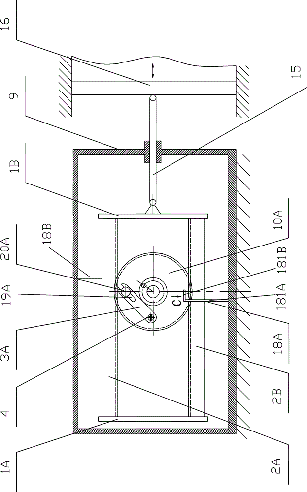
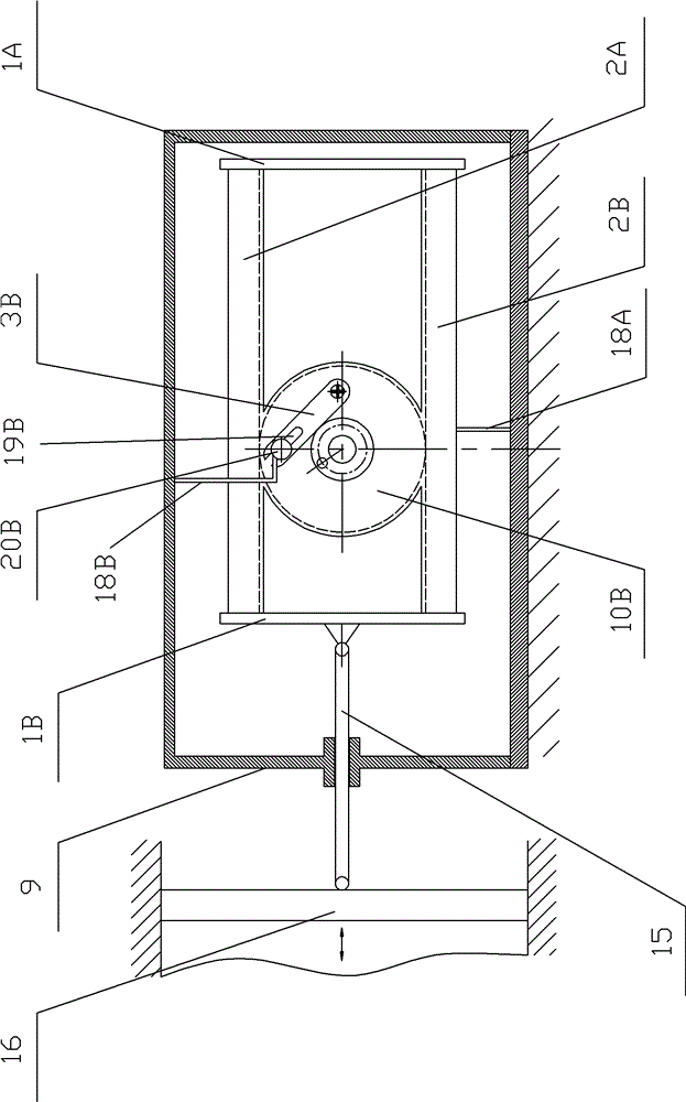
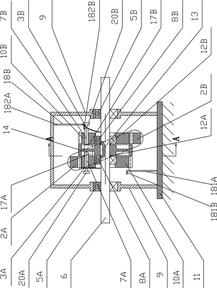
[0051] Such as Figure 2a , 2b , 2c, the second embodiment of the alternating drive conversion mechanism of linear reciprocating motion and rotary motion of the present invention differs from the first embodiment in that the first gear 10A' and the second gear 10B' are made into a semicircle The arc lengths of the first gear 10A' and the second gear 10B' can be set according to the linear reciprocating strokes of the first rack 2A and the second rack 2B respectively. Sliding pins 7A, 7B can be arranged on the edge positions of the first and second semicircular or fan-shaped gears respectively as shown in the figure, but it is better to be arranged on the center line of the semicircular or fan-shaped gears, so that the rotation of the gears will be more stable. The structure and movement process of the other parts of the second embodiment are the same as those of the first embodiment, and will not be repeated here.

[0052] Such as Figure 3a , 3b , 3c, 3d, and 3e, the thir...


PUM


Abstract

The invention discloses an alternative driving switching mechanism with linear reciprocating motion and rotating motion. A power driving wheel is fixedly arranged on a power output shaft; a first gear and a second gear are respectively arranged on two sides of a power driving gear on the power output shaft; a first rack is meshed with the first gear from the upper part of the power output shaft; a second rack is meshed with the second gear from the lower part of the power output shaft; two ends of the first rack and the second rack are respectively and fixedly arranged on a rack bracket; the rack bracket is connected with a power input connecting rod; and the first gear and the second gear can be alternatively connected or separated from the power driving wheel, so that the power driving wheel rotates along the same direction. The alternative driving switching mechanism disclosed by the invention can carry out mutual switch between the linear reciprocating motion and the rotating motion instead of a crankshaft-link mechanism, so that the switching efficiency between the piston action force and an output torque is increased, the lateral friction force and mechanical vibration between a piston and an air cylinder wall are reduced and the phenomenon of blocking the cylinder is avoided; and in addition, the dead center is overcome without using a flywheel, so that energy sources can be effectively saved.

Description

technical field [0001] The invention relates to an alternate drive conversion mechanism for linear reciprocating motion and rotary motion, in particular to a rack-gear and slider-slope groove combination drive conversion mechanism for mutual conversion between linear reciprocating motion and uniform circular motion. Background technique [0002] In mechanical engineering, such as piston engines, compressors and other machines that need to convert between linear reciprocating motion and circular motion, the crankshaft (crank) connecting rod mechanism is generally used at present. [0003] The design and manufacture of the traditional crankshaft (handle) linkage mechanism has been very perfect, but there are the following obvious shortcomings in both theoretical analysis and practical application: [0004] 1. The conversion efficiency of the crankshaft (handle) linkage mechanism is low. Taking the piston-connecting rod-crankshaft (handle) mechanism engine as an example, the g...

Claims


Application Information

Patent Timeline
Patent Type & Authority Patents(China)
IPC IPC(8): F16H37/12
Inventor 安里千刘庆毛灵涛
Owner 安里千
Why Eureka
Try Eureka