Ripple filter circuit of high-efficiency light emitting diode (LED) constant current source

A filter circuit and high-efficiency technology, applied in the field of LED lighting, can solve problems such as poor stability, complex structure, and large quantity, and achieve the effects of low cost, small size, and high filtering efficiency

Inactive Publication Date: 2012-10-24
厦门方光电子科技有限公司
View PDF3 Cites 4 Cited by
  • Summary
  • Abstract
  • Description
  • Claims
  • Application Information

AI Technical Summary

Problems solved by technology

[0007] Aiming at the deficiencies of the prior art, the present invention provides a ripple filter circuit of a high-efficiency LED constant current source, aiming to solve the problems of the LED constant current low ripple circuit with many components, large volume, complex structure, and stability in the prior art. To solve the problems of poor performance and low efficiency, provide an improved circuit for eliminating the ripple of LED constant current power supply, reduce the number of circuit components, reduce volume, reduce cost, reduce loss, and improve circuit reliability, work efficiency and filtering effect

Method used


Image

  • Ripple filter circuit of high-efficiency light emitting diode (LED) constant current source
  • Ripple filter circuit of high-efficiency light emitting diode (LED) constant current source

Examples


Embodiment 1

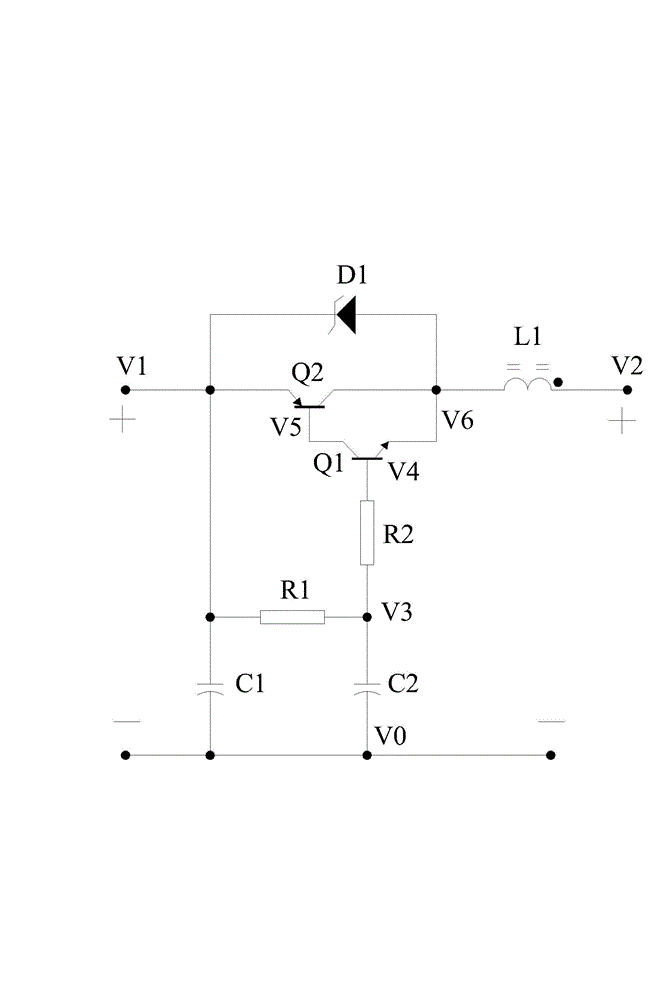
[0022] Embodiment 1, reference figure 1 As shown in the present invention, a high-efficiency LED constant current source ripple filter circuit, the ripple filter circuit is connected between the constant current switching transformer rectifier output and the LED load, the ripple filter circuit It is composed of capacitor C1, resistor R1, capacitor C2, resistor R2, triode amplifying unit, diode D1 and inductor L1. The triode amplifying unit is a secondary circuit composed of NPN type transistor Q1 and PNP type transistor Q2, wherein capacitor C1 Connected in parallel to the rectifier output end of the constant current switching transformer, resistor R1 and capacitor C2 are connected in series and then connected in parallel with capacitor C1, one end of resistor R2 is connected to the common end of the connection between resistor R1 and capacitor C2, and the other end of resistor R2 is connected to transistor Q1 The base of the transistor Q1, the collector of the transistor Q1 i...

Embodiment 2

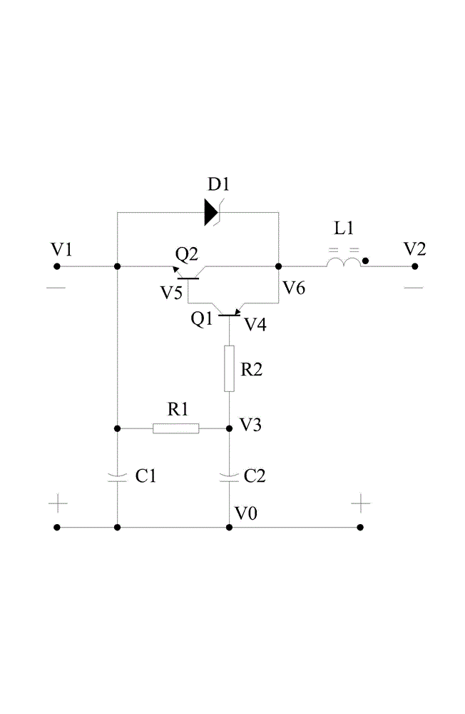
[0024] Embodiment 2, refer to figure 2As shown in the present invention, a high-efficiency LED constant current source ripple filter circuit, the ripple filter circuit is connected between the constant current switching transformer rectifier output and the LED load, the ripple filter circuit It is composed of capacitor C1, resistor R1, capacitor C2, resistor R2, triode amplifying unit, diode D1 and inductance L1. The triode amplifying unit is a secondary circuit composed of PNP type transistor Q1 and NPN type transistor Q2, wherein capacitor C1 Connected in parallel to the rectifier output end of the constant current switching transformer, resistor R1 and capacitor C2 are connected in series and then connected in parallel with capacitor C1, one end of resistor R2 is connected to the common end of the connection between resistor R1 and capacitor C2, and the other end of resistor R2 is connected to transistor Q1 The base of the transistor Q1, the collector of the transistor Q1 ...


PUM


Abstract

The invention relates to the technical field of light emitting diode (LED) lighting, in particular to a ripple filter circuit of a high-efficiency LED constant current source. According to principles of low sampling voltage of a bipolar junction transistor (BJT) and controllable and variable internal resistance of the BJT, current is detected by a resistor R2 and an inductor L1, and a detection result is accurately adjusted by a triode amplification unit, so low-frequency ripple and switching pulse ripple in the circuit are filtered, electric energy on an electrolytic capacitor constantly flows to an LED load, and the current which is obtained by the LED load can be pure constant current which is substantially free from the ripple. The ripple filter circuit of the high-efficiency LED constant current source has the advantages that the content of the low-frequency ripple is not more than 1 percent, and the filter efficiency can be between 97 percent and 99 percent. The ripple filter circuit is simple in structure, small in quantity of circuit elements, small in size, low in cost and high in circuit reliability and working efficiency, the insertion loss of the circuit is only 1 to 3 percent, and the cost performance of a product is greatly improved.

Description

technical field [0001] The invention relates to the technical field of LED lighting, in particular to a ripple filter circuit for realizing a high-efficiency LED constant current source. Background technique [0002] LEDs have high luminous efficiency and low energy consumption, making them the first choice for energy-saving lighting and the main trend in the use of energy-saving products in the future. Nowadays, most of the LED light strings with a large number adopt the constant current power supply method, which makes the LED luminous efficiency increase and the service life increase. However, ordinary LED constant current power supplies often have comprehensive ripples such as low-frequency ripples caused by low-frequency AC power and high-frequency pulse interference generated by their own switching circuits, but they cannot meet the ripple-free requirements of high-standard lighting standards. Lighting requirements, because the LED is a voltage-type load, a small volt...

Claims


Application Information

Patent Timeline
Patent Type & Authority Applications(China)
IPC IPC(8): H05B37/00
Inventor 刘开展
Owner 厦门方光电子科技有限公司
Why Eureka
Try Eureka