Rotor type pressure swing adsorption gas separation device

A pressure swing adsorption and gas separation technology, which is applied in the direction of dispersed particle separation, gas treatment, separation methods, etc., can solve the problems of increased investment, increased sulfur dioxide emissions, increased energy consumption, etc., and achieves easy operation, small amount of adsorbent, Effect of reducing operating energy consumption

Inactive Publication Date: 2012-10-31
南京圣火环境科技有限公司
View PDF8 Cites 27 Cited by
  • Summary
  • Abstract
  • Description
  • Claims
  • Application Information

AI Technical Summary

Problems solved by technology

Due to the need for frequent switching between multiple adsorption towers, the production capacity of the pressure swing adsorption device is limited, the energy consumption increases, the floor area is large, and the system is complex
[0005] At present, most of the kilns use air with an oxygen concentration of 21%, which contains 78% nitrogen that does not participate in combustion, taking away a large amount of combustion heat, reducing the combustion temperature, and improving The important thing is that due to the large amount of combustion air and flue gas, the investment in the kiln system equipment is enlarged. On the other hand, the emission of nitrogen oxides is increased due to the large amount of nitrogen entering the combustion zone, and the emission of sulfur dioxide is also increased due to insufficient oxygen concentration.

Method used


Image

  • Rotor type pressure swing adsorption gas separation device
  • Rotor type pressure swing adsorption gas separation device
  • Rotor type pressure swing adsorption gas separation device

Examples


Embodiment Construction

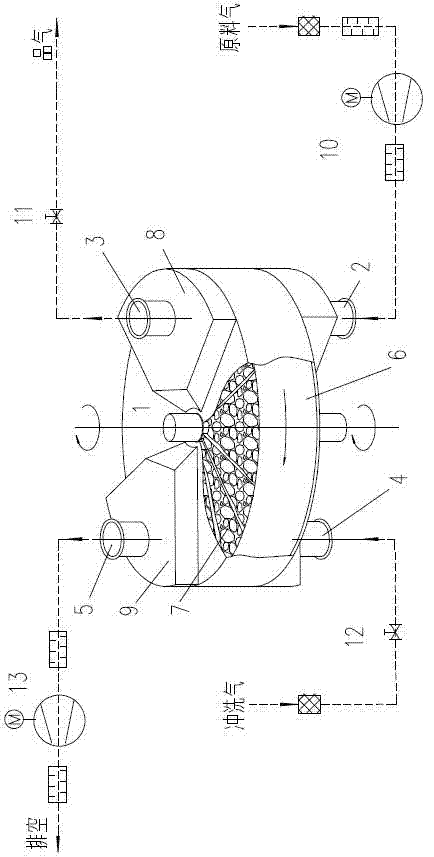
[0013] Control attached figure 1 , its structure includes a housing and a rotor 6,

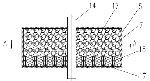
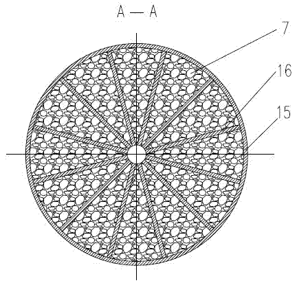
[0014] The rotor 6 is installed in the housing, and is divided into an adsorption zone 8 and a desorption zone 9 according to the different pressures formed; the rotor 6 is composed of a rotating shaft 14 and a hollow disc 15 fixed on the rotating shaft, and the disc 15 is composed of several The separator 16 forms a plurality of spaces, and the spaces are filled with the adsorbent 7 and closed with porous plates or nets 17 at both ends along the axial direction. In order to make the air flow evenly distributed and protect the adsorbent from strong air flow impact, a flow equalization layer 18 is provided on the air intake side of the space, so that the rotor disk is air-permeable in the axial direction and can rotate with the rotating shaft.

[0015] Raw gas inlet 2, product gas outlet 3, flushing gas inlet 4, and waste gas discharge port 5 are installed on the housing.

[0016] The rotor t...


PUM


Abstract

The invention discloses a rotor type pressure swing adsorption gas separation device, wherein a rotor is arranged in a shell; an adsorption region and a desorption region are divided according to formed different pressures; the rotor comprises a disc with a plurality of empty grids which is formed by a plurality of partition plates; the empty grids are filled with an adsorbent and are sealed by using porous plates or nets at the two ends in the axial direction; during work, the rotor rotates, an adsorbent is driven to continuously move and circulate at the adsorption region and the desorption region; feed gas and/or flushing gas regionally pass (passes) through the adsorbent layer in direction crossed with the adsorbent movement direction, so that the feed gas is continuously separated and purified at the adsorption region; and saturated adsorbent is continuously decompressed or/and flushed and regenerated at the desorption region, so that product gas is continuously and stably produced. The rotor type pressure swing adsorption gas separation device has the advantages of overcoming the defect of frequent switching of an adsorption tower existing in the conventional pressure swing adsorption gas separation device, low energy consumption, high yield, easiness in running and operation, small land occupation and small using amount of the adsorbent, is extremely suitable for the fields of oxygen enriched combustion, oxygen enriched and pure oxygen application of industrial kilns and can also be used for separation and purification industries of other gases.

Description

technical field [0001] The invention is a rotor-type pressure swing adsorption gas separation device, which is used in oxygen-enriched combustion or other oxygen-enriched and pure oxygen application industries, and can also be used in other gas separation and purification industries, which belongs to the gas separation and purification, oxygen-enrichment and pure oxygen application technology field. Background technique [0002] At present, there are three main methods for producing oxygen-enriched air: cryogenic method, membrane separation method and pressure swing adsorption method. The principle of the cryogenic method is low-temperature rectification, which compresses, cools, and liquefies air, and uses the difference in boiling points of different gases to carry out rectification to separate nitrogen and oxygen. This method was invented by Professor Linde in 1902. It is a traditional process of large-scale oxygen production and also the main method of large-scale indus...

Claims


Application Information

Patent Timeline
Patent Type & Authority Applications(China)
IPC IPC(8): B01D53/06
CPCB01D53/06B01D2256/12C01B13/0259
Inventor 罗义佳孔学标
Owner 南京圣火环境科技有限公司
Why Eureka
Try Eureka