Fuel injection executing valve

A fuel injection and actuating valve technology, which is applied to fuel injection devices, charging systems, engine components, etc., can solve the problems of low oil drainage capacity, insufficient oil drainage, and large liquid resistance on the suction surface, so as to improve the overall strength and accuracy, avoid cavitation bubbles, reduce the effect of liquid resistance

Inactive Publication Date: 2012-10-31
北京天纬燃油喷射技术股份有限公司
View PDF4 Cites 2 Cited by
  • Summary
  • Abstract
  • Description
  • Claims
  • Application Information

AI Technical Summary

Problems solved by technology

[0006] In the executive valve used in the above-mentioned prior art, although the outer circumference of the suction surface is provided with an oil passage, and the core of the suction surface is provided with an oil passage groove, but the arrangement of the oil passage and the oil passage (some adopt Staggered arrangement) and the shape and size often make the oil drainage capacity of the suction surface low, which will lead to problems such as insufficient oil drainage and large liquid resistance; and the unreasonable arrangement of the oil passage may generate a local low-pressure vacuum state, Air bubbles that are easy to form cavitation will adversely affect the reliability of parts; moreover, the oil passage design of the actuator valve in the prior art often only considers the oil drainage capacity index of the suction surface, and ignores the electromagnetic force. loss, that is, it cannot effectively ensure that the magnetic flux generated by the solenoid valve has sufficient flow area
[0007] In addition, the actuator valves in the prior art usually adopt a split structure, that is, the guide shaft is molded from casting materials, while the suction surface is made of silicon steel, and the outer circumference of the suction surface and the guide shaft is made of thermal sintering or Connected by welding, the shape tolerance and machining accuracy of this processed product are not easy to control, and the process is complicated, the reliability and durability need to be enhanced, and the manufacturing cost is high

Method used


Image

  • Fuel injection executing valve
  • Fuel injection executing valve
  • Fuel injection executing valve

Examples


Embodiment 1

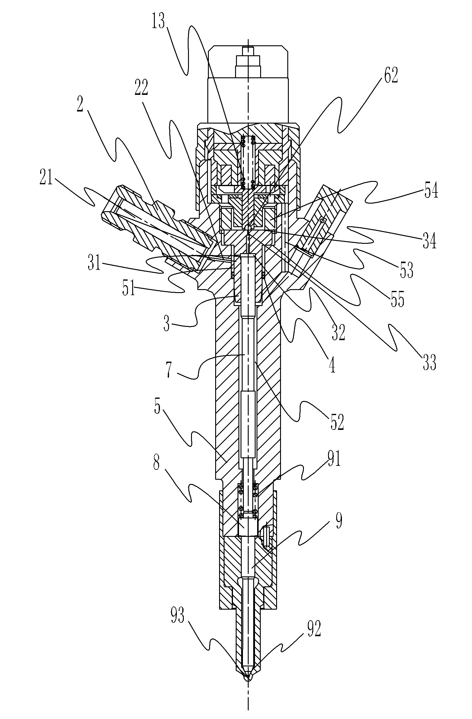
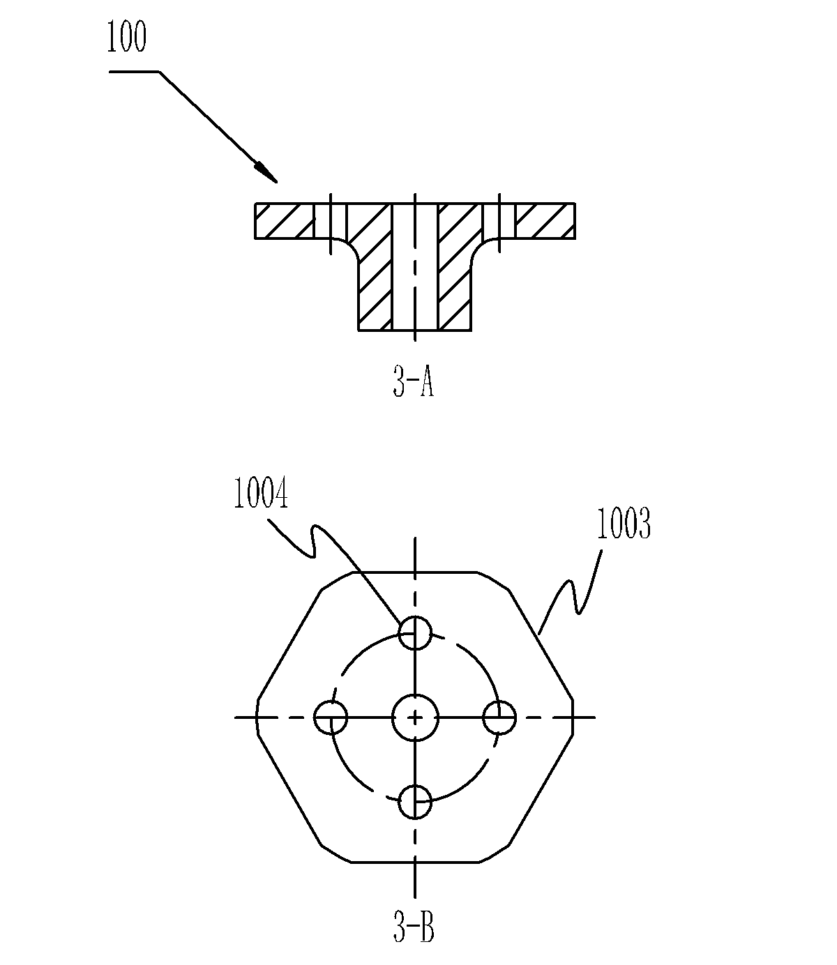
[0043] Such as Figure 4 As shown, the guide shaft 63A of the actuator valve in Embodiment 1 extends downward from the center of the back of the suction surface 61A, and cooperates with the guide sleeve 100 capable of magnetic isolation, so that the actuator valve 6A can slide vertically along the middle hole of the guide sleeve 100 ( refer to figure 1 , 3 ). The center hole of the guide sleeve is guided by the guide shaft 63A of the actuator valve 6A, the outer circle is guided by the solenoid valve cavity installed on the injector body, and the bottom of the hole of the injector body is used as the supporting surface, as shown in image 3 As shown in -B, the outer circle of the guide sleeve 100 is cut with an oil-passing hexagon 1003, and the guide sleeve 100 axially penetrates the guide sleeve oil-passing hole 1004 on the same circumference, and the position of the oil-passing hole is the same as that of the actuator valve oil-passing hole 66A There is a corresponding re...

Embodiment 2

[0052] Such as Figure 5 As shown, the actuator valve 6B involved in Embodiment 2 has an oil passage 64B that runs through the suction surface and the lower surface on the suction surface 61B. The difference from Embodiment 1 is that the oil passage 64B in Embodiment 2 is Long strip shape, that is, a straight groove opening is formed from the outer circle of the suction surface 61B toward the center, and the strip-shaped oil passages are regularly distributed on the radial circumference of the suction surface 61B. There is a circular recess 68B in the center of the suction surface 61B, which can be used to accommodate the solenoid valve spring 13 and play a supporting role for it. An annular contact surface is formed around the outer circumference of the circular recess 68B, and the annular contact surface is opposite. The annular protrusion 69B on the suction surface 61B is vertically raised by 0.05mm from the annular contact surface to the surface of the suction surface, and...

Embodiment 3

[0057] The structure difference from Embodiment 2 is that the oil passage 64C used by the executive valve 6C in Embodiment 3 is in the shape of a flask, and the mouth of the flask is located on the outer peripheral edge of the suction surface 61C. The circular parts of the flask-shaped oil passages respectively communicate with the three oil passages 65C arranged at intervals, and the centers of the circular parts of the three oil passages 64C are located on the same circumference, as Figure 6 shown by the dotted line inside. The circular part of the oil passage 64C and the oil passage 66C are alternately arranged, and the centers of the three oil passages 66C are located on the same circle, that is, as Figure 6 shown by the dotted line on the outside. Compared with Embodiment 2, the flask-shaped oil passage of this embodiment has a larger oil passage area, which will make the fuel liquid flow more smoothly, speed up the oil drain, and greatly reduce the displacement of the...


PUM


Abstract

The invention discloses a fuel injection executing valve which is a part of an electromagnetic valve used in a high-pressure storage type fuel supplying system. The electromagnetic valve is mounted on the upper portion of the fuel supplying system. The fuel injection executing valve comprises an attraction side, a guide shaft and fuel passages. The attraction side is attracted on the lower end face of a thrust sleeve of the electromagnetic when the electromagnetic valve is electrified. The guide shaft in cylindrical structure extends downwards from the center of the back of the attraction side, is penetratingly arranged in a central hole of a guide sleeve fixed in a valve chamber and can slide relatively to the central hole. The guide shaft and the attraction side are integrally formed. The fuel passages are in fuel passage structures communicated with the attraction side and used for guaranteeing that low-pressure fuel flowing out of a fuel outlet throttle hole is sufficiently discharged on the attraction side instantly the executing valve is at high-speed attraction. The fuel passages are uniformly circumferentially arranged along the attraction side at intervals and are communicated with a core portion of the attraction side directly or indirectly. By the executing valve, fuel discharge capability of the attraction side can be effectively guaranteed, electromagnetic force loss can be reduced to the greatest extent, and durability of the integrally formed executing valve is improved effectively.

Description

technical field [0001] The invention relates to an engine fuel supply system, in particular to an electromagnetically controlled fuel injection executive valve in an injector of the fuel supply system. Background technique [0002] Solenoid-controlled actuator valves are used in high-pressure accumulator fuel supply systems. Solenoid valves generally include an actuator valve and a coil. The coil receives the control signal from the engine control unit to control the opening and closing of the actuator valve. The actuator valve controls the pressure in the control chamber which controls the injector action. [0003] The coil is energized, the executive valve responds and moves, and an orifice is opened, which is the oil outlet of the valve body control chamber to control the pressure in the control chamber, which is applied to the matched valve in the control valve body. Control the plunger and the needle valve of the nozzle, so that the displacement of the control plunge...

Claims


Application Information

Patent Timeline
Patent Type & Authority Applications(China)
IPC IPC(8): F02M61/12
Inventor 臧微李春燕陈晓辉尚伟
Owner 北京天纬燃油喷射技术股份有限公司
Why Eureka
Try Eureka