
Transient state intensifier circuit applicable for capacitance-free large power low voltage difference linear voltage regulator

A low-dropout voltage regulator, low-dropout linear technology, used in instruments, regulating electrical variables, control/regulating systems, etc., can solve the problems of small load current variation range, large chip area, large resistance value, etc., to achieve fast response , The effect of occupying small chip area and simple structure

Active Publication Date: 2012-10-31
EAST CHINA INST OF OPTOELECTRONICS INTEGRATEDDEVICE
View PDF5 Cites 7 Cited by
  • Summary
  • Abstract
  • Description
  • Claims
  • Application Information

AI Technical Summary

Problems solved by technology

[0005] The patent application with the application number 200610023879.7 discloses a method to speed up the output voltage of the LDO, but the variation range of the load current is small, and the maximum load is only 100mA; at the same time, in order to reduce the additional static power consumption, the resistance of the comparison potential is generated The voltage divider network requires a larger resistance value, which undoubtedly occupies a larger chip area

Method used


Image

  • Transient state intensifier circuit applicable for capacitance-free large power low voltage difference linear voltage regulator
  • Transient state intensifier circuit applicable for capacitance-free large power low voltage difference linear voltage regulator
  • Transient state intensifier circuit applicable for capacitance-free large power low voltage difference linear voltage regulator

Examples


Embodiment 1

[0023] Embodiment one: see attached figure 1 shown.

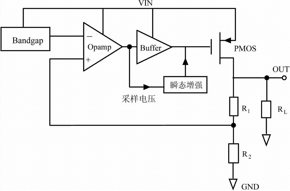
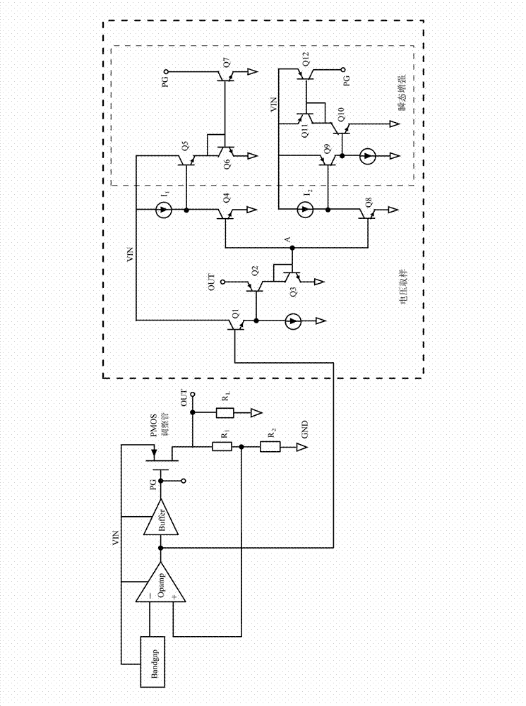
[0024] A transient enhancement circuit suitable for a non-capacitor-type high-power low-dropout linear voltage regulator is connected with the non-capacitor-type high-power low-dropout linear voltage regulator.

[0025] The low-dropout linear regulator includes a bandgap reference voltage source Bandgap, an operational amplifier Opamp, a buffer circuit Buffer, a power regulator PMOS, and a feedback resistor network. The bandgap reference voltage source Bandgap is connected to the inverting input terminal of the operational amplifier Opamp, the output terminal of the operational amplifier Opamp is connected to the input terminal of the buffer circuit Buffer, and the output terminal of the buffer circuit Buffer is connected to the gate of the power adjustment transistor PMOS , the source of the power adjustment transistor PMOS is connected to the bandgap reference voltage source Bandgap, the drain of the power adjustment tra...


PUM


Abstract

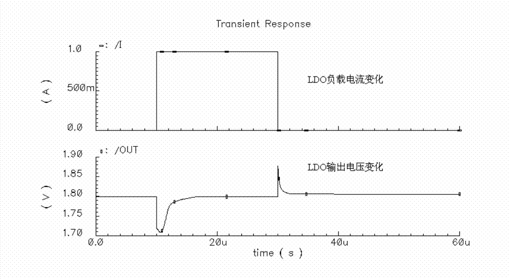
The invention relates to a transient state intensifier circuit applicable for a capacitance-free large power low voltage difference linear voltage regulator. The low voltage difference linear voltage regulator comprises a power adjusting tube; the transient state intensifier circuit comprises a voltage sampling part and a transient state intensifying part; the voltage sampling part is connected with an output end of the low voltage difference linear voltage regulator; an input end of the transient state intensifying part is connected with the voltage sampling part; an output end of the transient state intensifying part is connected with the grid of the power adjusting tube; when the low voltage difference linear voltage regulator changes from the light load to the heavy load, the level of the grid of the power adjusting tube is pulled down by the transient state intensifying part and an output voltage of the lowered low voltage difference linear voltage regulator is recovered; and when the low voltage difference linear voltage regulator changes from the heavy load to the light load, the level of the grid of the power adjusting tube is risen by the transient state intensifying part and the output voltage of the risen low voltage difference linear voltage regulator is recovered. The transient state intensifier circuit is simple in structure; a static power consumption current of the low voltage difference linear voltage regulator is hardly increased; and the rapid response of the low voltage difference linear voltage regulator is realized.

Description

technical field [0001] The invention relates to a circuit capable of realizing fast transient response for a non-capacitor low-dropout linear regulator circuit. Background technique [0002] LDO (Low Dropout Voltage Regulator: Low Dropout Voltage Regulator) is the simplest linear regulated power supply. It has the advantages of small size, low noise, low output ripple, no electromagnetic interference, simple design, and few peripheral components. [0003] Compared with the traditional LDO, the biggest difference of the non-capacitor LDO is that the circuit structure lacks a large capacitor connected in parallel at the output end. In a traditional LDO, the large capacitor at the output is a very important charge storage and supply device, which can effectively reduce the output voltage drop and voltage overshoot due to the step change of the load current. For the capless LDO, the step change of the load must rely on the fast response of the pass transistor, that is, the gate...

Claims


Application Information

Patent Timeline
Patent Type & Authority Applications(China)
IPC IPC(8): G05F1/56
Inventor 白涛龙善丽李秋丽陈超赵杰武风芹
Owner EAST CHINA INST OF OPTOELECTRONICS INTEGRATEDDEVICE
Learn More