Device and method for removing suspended-material particles

A technology for suspending substances and particles, applied in the direction of chemical instruments and methods, devices in which the axial direction of the swirl remains unchanged, separation methods, etc.

Inactive Publication Date: 2012-10-31
VIENNA UNIVERSITY OF TECHNOLOGY
View PDF9 Cites 1 Cited by
  • Summary
  • Abstract
  • Description
  • Claims
  • Application Information

AI Technical Summary

Problems solved by technology

However, the unit was not designed to remove suspended matter particles from pressurized water lines in power plants

Method used


Image

  • Device and method for removing suspended-material particles
  • Device and method for removing suspended-material particles
  • Device and method for removing suspended-material particles

Examples


Embodiment Construction

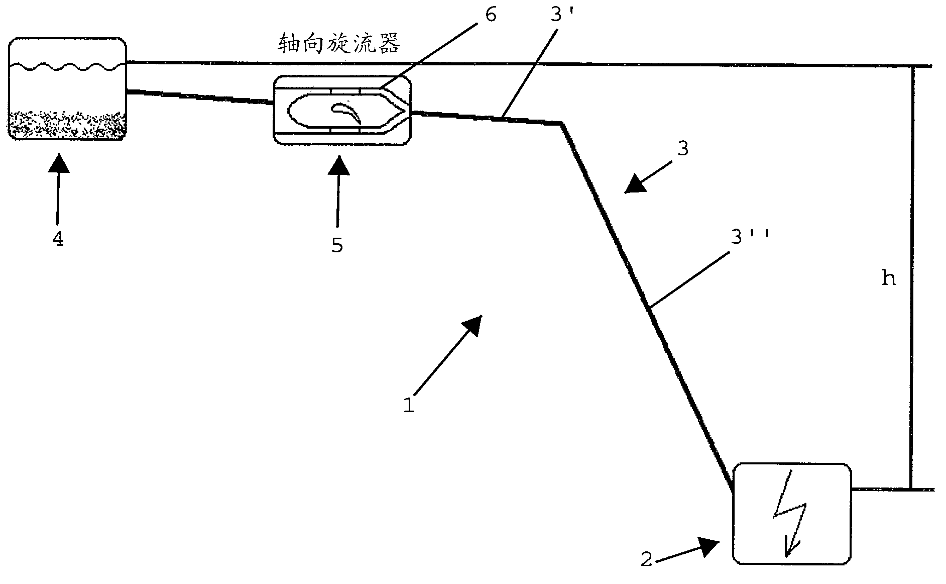
[0047] figure 1 A hydroelectric power plant 1 is shown schematically, by means of which hydroelectric energy is converted into electricity in a conventional manner. The hydroelectric plant 2 is connected to a pressurized water line 3 which is supplied with water from a reservoir in which the water is held at a high potential energy level whereby in the illustrated example of an embodiment the pressurized The water line 3 has two sections 3', 3", which have different slopes. The pressurized water line 3 can be connected directly to the water of a reservoir, or as figure 1 As schematically shown in , it is connected to a conventional desanding settling basin 4 for removing coarser solids such as sand grains, sand particles, and the like. When the sluice or closing element of the reservoir is opened, the water flows down via the pressurized water line 3 and obtains flow energy according to the drop h, which can then be used to operate the turbines provided in the hydroelectric p...


PUM


Abstract

The invention relates to a device (5) and method for removing suspended-material particles, in particular fine and very fine particles, from a water flow containing suspended-material particles in a pressurized water line (3) of a hydroelectric power plant (2), wherein a tubular element (6) that forms a flow channel (7) is provided in the pressurized water line (3), wherein the flow channel (7) extends substantially in the axial direction of the pressurized water line (3), and a stationary swirl-generating device (11) is arranged in the flow channel (7) in order to generate a flow component of the water flow perpendicular to a main flow direction (9), and a separating device (13) for separating the suspended-material particles carried radially outward due to the centrifugal force effect is provided after the swirl-generating device (11) in the flow direction.

Description

technical field [0001] The present invention relates to a device and a method for removing suspended matter particles, in particular sand, from a water stream containing suspended matter particles in a pressurized water line of a hydroelectric power plant. Background technique [0002] A hydroelectric power plant converts the hydraulic energy of water flow into electrical current. Storage hydropower plants use the potential energy of a reservoir by accelerating water along pressurized water pipes over a drop of several hundred meters. The kinetic energy of the water flow is converted into rotational energy by a turbine and used as electrical energy by means of a generator. Reservoirs may contain large amounts of sediment or suspended matter particles, ie solid matter of different sizes, such as silt, sand, etc., which reach the power plant via pressurized water lines, causing high wear on rotating parts especially of turbines. [0003] In order to prevent the sensitive par...

Claims


Application Information

Patent Timeline
Patent Type & Authority Applications(China)
IPC IPC(8): B04C3/00B04C3/06E02B9/06
CPCF03B11/00Y02E10/226B04C3/06Y02E10/223B04C3/00B04C2003/006F03B3/18E02B9/06Y02E10/22F05B2260/63Y02E10/20B01D21/267C02F1/38
Inventor 爱德华·杜亚克贝恩德·温德霍尔茨利奥波德·宾德尔
Owner VIENNA UNIVERSITY OF TECHNOLOGY
Why Eureka
Try Eureka