Fly cutter plate for processing large-size optical elements by single-point diamond milling method

A single-point diamond and milling technology, which is applied in the field of flying cutters, can solve the problems of lattice damage, reduce processing efficiency, and increase processing costs, so as to reduce lattice damage, ensure cutting effect, and facilitate adjustment. Effect

Active Publication Date: 2012-11-07
NAT UNIV OF DEFENSE TECH
View PDF5 Cites 7 Cited by
  • Summary
  • Abstract
  • Description
  • Claims
  • Application Information

AI Technical Summary

Problems solved by technology

However, according to literature reports, when milling anisotropic brittle materials such as KDP crystals, the cutting effect is best when the rake angle of the tool is in the range of -25° to -45°, otherwise the crystal lattice will be damaged to varying degrees. Abnormal cutting effect is formed, resulting in deep scratch damage on the crystal surface
At present, the tools in SPDT technology are all fixed on the flying cutter head at a certain angle, and the adjustment of the rake angle of the tool cannot be realized.
In addition, if the cutting edge of the diamond tool is worn when processing brittle materials, the quality of the machined surface will be reduced, and the current flying cutter head cannot change the effective cutting angle of the tool. After the tool is worn, it needs to be replaced or sharpened before use. This increases the processing cost and reduces the processing efficiency

Method used


Image

  • Fly cutter plate for processing large-size optical elements by single-point diamond milling method
  • Fly cutter plate for processing large-size optical elements by single-point diamond milling method
  • Fly cutter plate for processing large-size optical elements by single-point diamond milling method

Examples


Embodiment Construction

[0020] The present invention will be described in further detail below in conjunction with the accompanying drawings and specific embodiments.

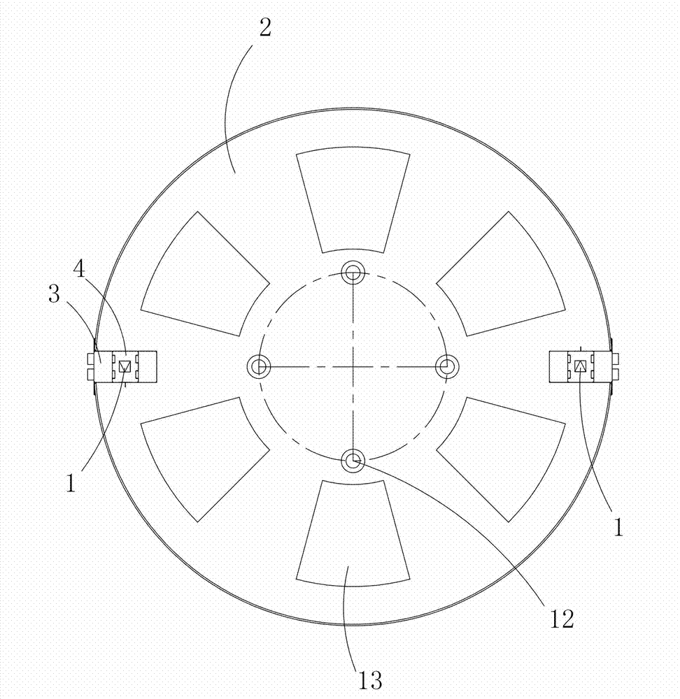
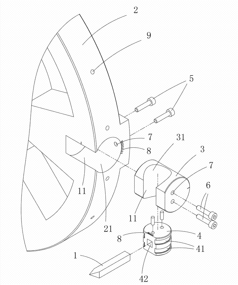
[0021] like figure 1 , figure 2 As shown, an embodiment of a flying cutterhead used for single-point diamond milling of the present invention to process large-sized optical elements includes a flying cutterhead body 2, a diamond cutter 1, and a cylindrical rake angle adjustment for installing the diamond cutter 1 Block 3. The flying cutter head body 2 is provided with evenly distributed countersunk holes 12 and lightening holes 13 , and the countersunk holes 12 are used for connecting the flying cutter head body 2 with the spindle of the milling machine. The outer circumference side of the flying cutter head body 2 is provided with two cylindrical grooves 21 along the radial direction of the flying cutter head body 2, and the front angle adjustment block 3 is rotatably sleeved in the cylindrical grooves 21 and passed through the fi...


PUM


Abstract

The invention discloses a fly cutter plate for processing large-size optical elements by a single-point diamond milling method. The fly cutter plate comprises a fly cutter plate body, a diamond cutter and a cylindrical front angle adjusting block for mounting the diamond cutter, wherein a cylindrical groove is arranged on the fly cutter plate body and is arranged in the radial direction of the fly cutter plate body; and the front angle adjusting block can be rotationally sleeved in the cylindrical groove and is fastened and located through a first fastening piece. The fly cutter plate is simple in structure and convenient to adjust, can flexibly adjust the front cutting angle of the diamond cutter and improves the cutting effect.

Description

technical field [0001] The invention mainly relates to the field of ultra-precision machining of brittle optical elements, in particular to a flying cutter used for processing large-sized optical elements by a single-point diamond milling method. Background technique [0002] In laser nuclear fusion devices, in order to improve the efficiency of nuclear fusion reactions, it is necessary to use a large number of electro-optical and nonlinear optical material elements, such as KDP crystals, K9 glass, quartz glass, etc. Most of these optical components are brittle materials, and single point diamond turning (SPDT) technology is currently a better processing method for processing brittle materials, especially for Pockels cells and nonlinear frequency conversion components. The brittle material KDP crystal, the SPDT method has become the first choice for this crystal processing method because of its advantages such as no sagging. However, according to literature reports, when mi...

Claims


Application Information

Patent Timeline
Patent Type & Authority Applications(China)
IPC IPC(8): B28D5/02C03B33/00
Inventor 李圣怡关朝亮朱登超彭小强戴一帆
Owner NAT UNIV OF DEFENSE TECH
Why Eureka
Try Eureka