Hydraulic clutch brake device of punch press

A braking device and hydraulic technology, applied in the combination of coupling and brake, presses, manufacturing tools, etc., can solve the problems of difficult to ensure assembly accuracy, difficult processing, and difficult sealing, and improve the performance of the product. The effect of force relationship, reduction of processing steps, and simplification of the overall structure

Active Publication Date: 2012-11-07
YANGZHOU FORGING MACHINE TOOL
View PDF6 Cites 12 Cited by
  • Summary
  • Abstract
  • Description
  • Claims
  • Application Information

AI Technical Summary

Problems solved by technology

[0004] However, from the perspective of implementation, the technical solution has the following problems: one is the complex structure and many parts; several tension spring type elastic return devices (return rods) are arranged on the hydraulic cylinder surface; the other is the annular piston, The sealing arc of the axial movement between the annular piston chamber is large, which makes the sealing extremely difficult, and the phenome

Method used


Image

  • Hydraulic clutch brake device of punch press
  • Hydraulic clutch brake device of punch press
  • Hydraulic clutch brake device of punch press

Examples


Embodiment Construction

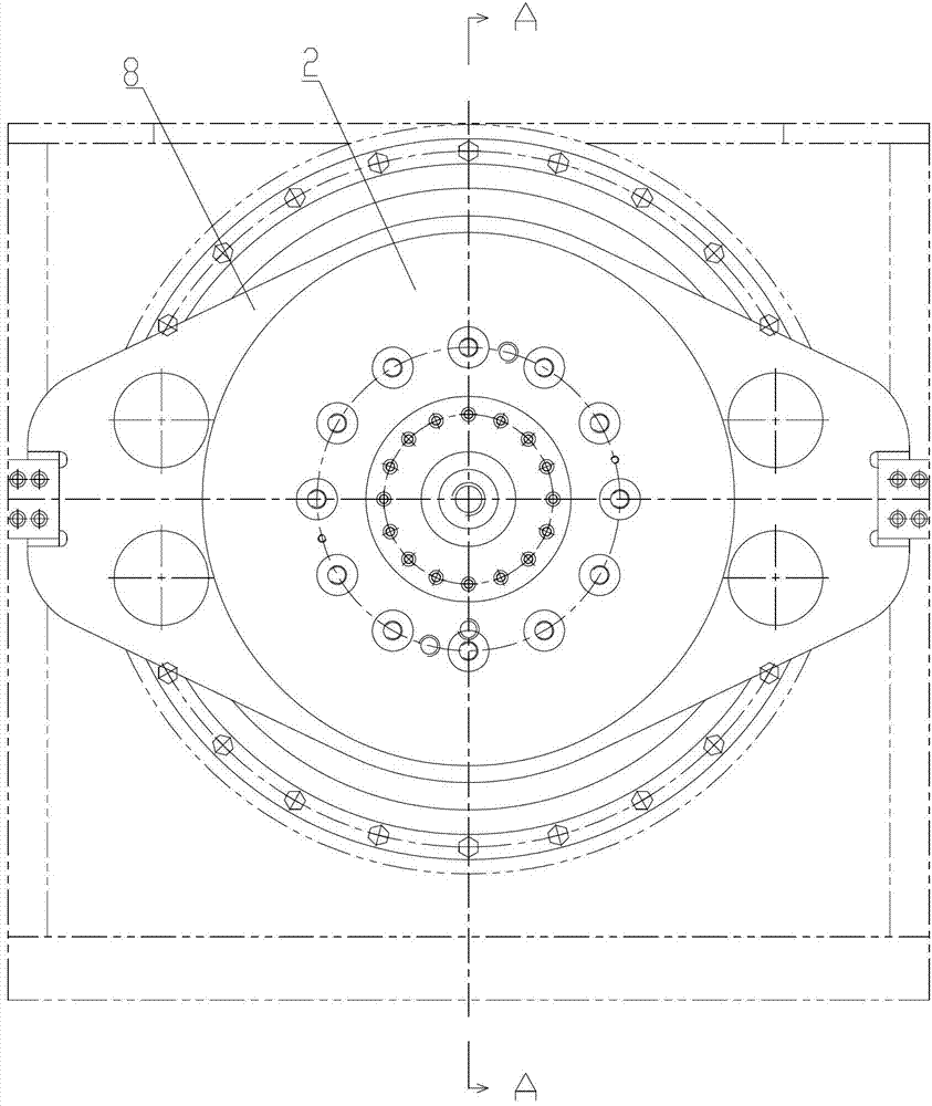
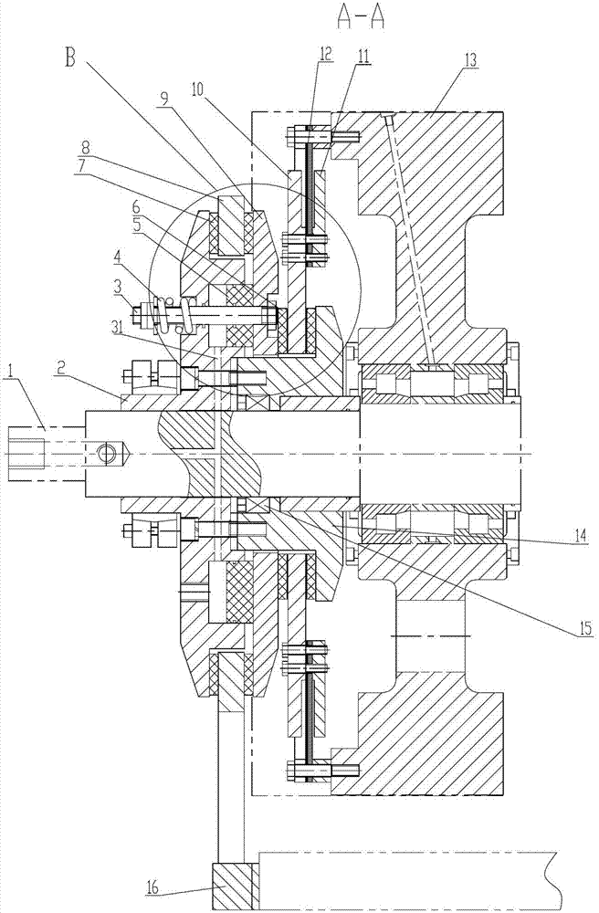
[0044] The present invention as Figure 1-18 Shown, a kind of hydraulic clutch braking device of punching machine, described punching machine comprises fuselage 16, flywheel 13, crankshaft 1 and hydraulic pressure source;

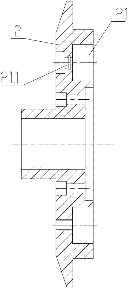
[0045] The hydraulic clutch brake device is provided between the crankshaft 1 and the flywheel 13, and the hydraulic clutch brake device includes a hydraulic cylinder 2, a working ring 9, a clutch plate 10, a spring steel plate 12 and a support sleeve 14;

[0046] The support sleeve 14 and the hydraulic cylinder 2 are sequentially fixedly connected to the crankshaft 1, the hydraulic cylinder 2 and the support sleeve 14 are fixedly connected, and the support sleeve 14 is provided with a large step circle, and the large step The distance between the outer end surface of the circle facing the hydraulic cylinder 2 and the inner end surface of the hydraulic cylinder 2 facing the support sleeve 14 is fixed;

[0047] The working ring 9 and the clutch plate 10 are...


PUM


Abstract

The invention discloses a hydraulic clutch brake device of a punch press and relates to improvement of the hydraulic clutch brake device of the punch press. According to the hydraulic clutch brake device of the punch press, a forward driving mechanism and a reverse driving mechanism are integrated, so that the whole structure is simple, the stress state can be improved, and the service life of parts can be prolonged. The punch press comprises a machine body, a flywheel, a crankshaft and a hydraulic source, the hydraulic clutch brake device is arranged between the crankshaft and the flywheel, a brake ring is fixedly arranged on the machine body, a hydraulic cylinder is connected with an operating ring through an axial opening/closing moving driving mechanism, the axial opening/closing moving driving mechanism comprises a piston rod, a piston and a return spring, and the piston rod also serves as a return guide rod. According to the hydraulic clutch brake device of the punch press, the return rod and the piston rod are integrated, and in order to ensure that the separation is clear, a clutch plate of the device and the flywheel of the device are connected through a steel spring plate, so that the clutch plate is effectively separated from a starting friction plate.

Description

technical field [0001] The invention relates to an improvement on the structure of a hydraulic clutch and brake device for a hydraulic clutch and brake press. Background technique [0002] The applicant submitted a utility model patent application with the application number 200820161074.3 and the name "hydraulic clutch brake device" to the State Intellectual Property Office on November 17, 2008. The purpose of this case is to enable the press to quickly realize full-speed high-speed operation and rapid braking, and at the same time, it is not easy to leak oil. The following technical scheme is proposed: "The rotary motion of the flywheel movably connected to the crankshaft is selectively transmitted to the crankshaft movably connected to the fuselage, which includes a clutch plate set on the end face of the flywheel and moves simultaneously with the flywheel, a fixed setting The hydraulic cylinder and braking device on the crankshaft, the hydraulic cylinder includes an ann...

Claims


Application Information

Patent Timeline
IPC IPC(8): F16D67/04B30B15/10
Inventor 赵宏松王伟陈春
Owner YANGZHOU FORGING MACHINE TOOL
Why Eureka
Try Eureka