Low voltage ride through control method for network side inverter of permanent magnet direct drive wind power system

A wind power system, permanent magnet direct drive technology, applied in wind power generation, single grid parallel feeding arrangement, etc., can solve the problems of unloading load circuit and SVC expensive, long time to collect information, low adjustment accuracy, etc., to improve The effect of low voltage ride through ability, fast and stable DC bus voltage, and simple principle of control method

Inactive Publication Date: 2012-11-07
LANZHOU JIAOTONG UNIV
View PDF2 Cites 13 Cited by
  • Summary
  • Abstract
  • Description
  • Claims
  • Application Information

AI Technical Summary

Problems solved by technology

[0005] 1. Complicate the system, reduce reliability, unload load circuit and SVC are expensive, and increase cost and volume;
[0006] 2. When the grid-connected voltage drops, the working mode needs to be changed, and the grid voltage needs to be monitored quickly and accurately. At the same time, uncontrollable factors of the system are added during the conversion process, which brings transient disturbance to the system;
[0007] 3. It is not easy to determine the timing and degree of unloading load and SVC delivery, the adjustment accuracy is not high, and the adjustment time is long
For the control method, it takes a long time to collect the DC bus voltage as the voltage outer loop. Since the capacitor voltage is collected, the capacitor voltage cannot change suddenly, so the time to collect information is long, the response is slow, and there is a hysteresis phenomenon.

Method used


Image

  • Low voltage ride through control method for network side inverter of permanent magnet direct drive wind power system
  • Low voltage ride through control method for network side inverter of permanent magnet direct drive wind power system
  • Low voltage ride through control method for network side inverter of permanent magnet direct drive wind power system

Examples


Embodiment Construction

[0033] The present invention will be described in detail below in conjunction with specific embodiments.

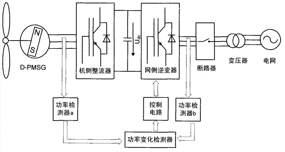
[0034] figure 1 It is the schematic diagram of grid-side inverter control. It includes power detector a, power detector b, power change detector and control circuit. in:

[0035] The power detector a is used to continuously monitor the output power of the wind turbine and provide an output signal proportional to the output power of the wind turbine;

[0036] The power detector b is used to continuously monitor the output power of the grid-side inverter and provide an output signal proportional to the output power of the grid-side inverter;

[0037]The power change detector is used to receive the output signals of power detectors a and b to record the power change. There is a comparator in the power change detector to compare the output power of the wind turbine and the output power of the grid-side inverter to generate actual power The difference signal ΔP is input to...


PUM


Abstract

The invention discloses a low voltage ride through control method for a network side inverter of a permanent magnet direct drive wind power system. The low voltage ride through control method comprises a power detector a, a power detector b, a power change detector and a control circuit are adopted, wherein the power change detector is used for receiving output signals from the power detectors a and b to record power changes; a comparator is arranged in the power change detector and is used for comparing an output power of a wind motor and an output power of a network side inverter to generate a practical power difference signal delta P, and inputting the signal delta P into an outer loop controller of the control circuit; and the control circuit is used for realizing current decoupling and generating a PWM (pulse width modulation) control signal to drive the inverter. According to the control method using a power outer loop, stability of the system during a voltage drop and a grid connection period can be guaranteed, reactive power can be compensated along with the power grid drop depth, and overcurrent of the network side inverter can be limited at the same time, therefore, the network side inverter can be guaranteed to work stably.

Description

technical field [0001] The invention relates to a low-voltage ride-through control method for a grid-side inverter of a permanent magnet direct-drive wind power system. Background technique [0002] Wind energy is a renewable energy source. It is estimated that the theoretical storage capacity of wind energy on the earth is about 2.74×10 9 MW, the wind energy that can be developed and utilized is 2×10 7 MW, as long as 1% of the wind energy on the earth is used, the global energy demand can be met. However, wind energy is an intermittent energy source, which is unstable and has large regional differences. In addition, my country's wind power industry started late and the level of localization is not high. In particular, there are still many problems in my country's wind power grid connection technology. Frequently, it exposes the lack of low-voltage ride-through capability of current wind turbines. All countries have issued corresponding standards for low-voltage ride-throug...

Claims


Application Information

Patent Timeline
IPC IPC(8): H02J3/38
CPCY02E10/763Y02E10/76
Inventor 张友鹏董唯光郭瑾高锋阳刘景利叶爱贤李萌赵斌
Owner LANZHOU JIAOTONG UNIV
Why Eureka
Try Eureka