Electrothermal drive outer rotor stepping micro-motor

An electrothermal drive, external rotor technology, applied in the direction of electrical components, electromechanical devices, etc., can solve the problems of difficult direct application of MEMS devices, difficult miniaturization of structure, and inability to directly apply, etc., to achieve large output force, novel and unique structure, easy to use The effect of control

Inactive Publication Date: 2012-11-07
SHANGHAI UNIV
View PDF6 Cites 5 Cited by
  • Summary
  • Abstract
  • Description
  • Claims
  • Application Information

AI Technical Summary

Problems solved by technology

In 1988, researchers at the University of California, Berkeley used the surface silicon process to make a 120-diameter The electrostatic micromotor is the earliest motor in the MEMS field. It directly uses the electrostatic force to drive the rotor. It can be miniaturized and compatible with the MEMS process, but the output torque is small and the speed is high, so it cannot be directly applied. In the US patent, Muller et al The patent "Micro Motor and Method for Their Fabrication (Patent No.: 5252881)" is a micro motor driven by electrostatic force
Electromagnetic induction micro motors have large output torque and fast speed, but the coil loss is large, and the structure is not easy to miniaturize; ultrasonic motors and surface acoustic wave motors have also done a lot of research at home and abroad in recent years
These motors have their own characteristics, but it is difficult to directly apply them to MEMS devices

Method used


Image

  • Electrothermal drive outer rotor stepping micro-motor
  • Electrothermal drive outer rotor stepping micro-motor
  • Electrothermal drive outer rotor stepping micro-motor

Examples


Embodiment 1

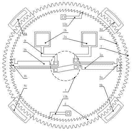
[0023] join figure 1 and figure 2 , the electrothermally driven outer rotor stepping micromotor, including a stator and a rotor (5), is characterized in that: the stator is an electrothermal actuator (3a, 3b) with cold and hot arms, and the rotor (5) is a ring wheel; One end of the actuator (3a, 3b) is fixed on the silicon substrate plane (12) through an anchor point, and the other end is a movable driving pawl (4a, 4b), and the ratchet teeth of the driving pawl (4a, 4b) It meshes with the inner ratchet (6) of the rotor (5), there is a gap between the driving pawls (4a, 4b) and the inner ratchet (6), the rotor (5) is a floating wheel, and there are standard involute gear teeth on the outer periphery (7), constrained by four uniformly distributed confinement hoods (8a, 8b, 8c, 8d), the fixed electrodes (2a, 2b) are electrically connected to the anchor point (1) through wires (9), and are connected to the hot and cold arms The electrothermal actuators (3a, 3b) are powered.

Embodiment 2

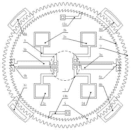
[0025] join figure 1 , figure 2 and image 3 , the present embodiment is basically the same as Embodiment 1, and the special features are as follows:

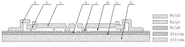
[0026] The hot and cold arm electrothermal actuators (3a, 3b) are U-shaped single-arm electrothermal actuators, or U-shaped double-arm electrothermal actuators. The number of the hot and cold arm electrothermal actuators can be 2, 4 or 6. The inner side of the rotor (5) is further provided with 1~2 stop ratchets (13a, 13b) meshing with the inner ratchet (6) of the rotor (5). The stator and rotor (5) are prepared by MEMS surface technology, on the silicon substrate plane (12), there is a silicon nitride layer (11), and on the silicon nitride layer (11) there is a fixed polysilicon layer used as a wire Poly0 (9), on the polysilicon layer Poly0 (9), there is a fixed structural layer Poly2 constituting the constraint cover (8a, 8b, 8c, 8d) and the anchor point (1) of the structural layer Poly1, on Poly0 (9) there is a The str...

Embodiment 3

[0028] In this micro-motor, in the initial state, the driving pawl 4, the stop pawl 13 and the triangular ratchet 6 on the inner wall of the rotor 5 are in the meshing state (due to technological reasons, there is a gap at the meshing part of the ratchet), and the electrode 2 is used to feed the actuator 3 power supply. The working principle of the micro-motor is: after the electrodes are energized, there is a current passing through the actuator. Since the actuators of the cold and hot arms are not equal in width, the resistance heat generated by the hot arm 15 is greater than that of the cold arm 16, so the actuator is under the resistance thermal stress. Under the action of Figure 5 As shown in the flexible arc movement, the driving pawl can drive the rotor to rotate clockwise through a certain angle. When the driving pawl returns, the ratchet of the pawl passes through the ratchet of the rotor, while the stationary driving pawl or stop pawl starts and stops For action, t...


PUM


Abstract

The invention relates to an electrothermal drive outer rotor stepping micro-motor, which comprises electrothermal actuators and a ring wheel rotor. The electrothermal actuators are flexible cold and hot arm electrothermal actuators and can make arc-shaped reciprocating motion. The rotor is a ring wheel and is supported on a substrate through anti-sticking bumps. The direction of the rotor in perpendicular to the substrate is constrained by constraint covers. Ratchets are arranged on the inner wall of the rotor. Gear teeth are arranged on the outer wall of the rotor. The micro-motor is driven by the electrothermal actuators and has the characteristics of large output torque, low rotating speed, small operating voltage, IC (integrated circuit) voltage compatibility and adjustable rotating speed. Since the micro-motor is fabricated by adopting the MEMS (micro-electromechanical system) surface silicon technology, the micro-motor is not required to be assembled, the structure is simple and the micro-motor can be used in the fields of medical treatment, military, aerospace, biomedicine and the like.

Description

technical field [0001] The invention relates to micro-actuators in the technical field of micro-electro-mechanical systems (MEMS), in particular to a stepping micro-motor driven by electric heating with an outer rotor. Background technique [0002] In recent years, with the continuous development and maturity of MEMS technology, the demand for micro motors with large output torque, simple structure and suitable speed has gradually increased. The requirements for micro-motors in various applications are different. For example, micro-motors used in optical and precision mechanical systems for precise driving and positioning of components require high speed, fast response, and miniaturization; micro-motors used in the aerospace field , requires large output torque, high efficiency, light weight, small size, long life, and high reliability; micro-motors used in the field of micro-nano technology require large torque, miniaturization, high efficiency, and appropriate motor speed....

Claims


Application Information

Patent Timeline
Patent Type & Authority Applications(China)
IPC IPC(8): H02K37/24
Inventor 沈雪瑾王振禄周玲陈晓阳胡懿
Owner SHANGHAI UNIV
Why Eureka
Try Eureka