Insulating composite wall body of building

A composite wall and building thermal insulation technology, which is applied in thermal insulation, construction, building components, etc., can solve the problems of inconvenient connection of concrete-supported cantilever beams, inconvenient construction, poor fire prevention of curtain wall decoration, etc., and increase energy-saving and thermal insulation effects , Convenience in construction, beneficial to the anti-seismic effect of buildings

Inactive Publication Date: 2012-11-14
吴淑环
View PDF8 Cites 0 Cited by
  • Summary
  • Abstract
  • Description
  • Claims
  • Application Information

AI Technical Summary

Problems solved by technology

Therefore, whether it is cast-in-place installation or prefabricated installation of concrete-supported cantilever beams, the construction is very inconvenient, which becomes an obstacle to adopting concrete-supported cantilever beams
[0023] 2), the concrete support cantilever beam is inconvenient to connect with the steel structure
[0025] 3. At present, the technology of energy-saving and thermal insulation wall curtain wall decoration and installation has not been solved, and the fire prevention of curtain wall decoration is not good. For example, the fire in the CCTV building and the fire in Shenyang Wanxin Restaurant means that the insulation layer in the curtain wall burns

Method used


Image

  • Insulating composite wall body of building
  • Insulating composite wall body of building
  • Insulating composite wall body of building

Examples


Embodiment 1

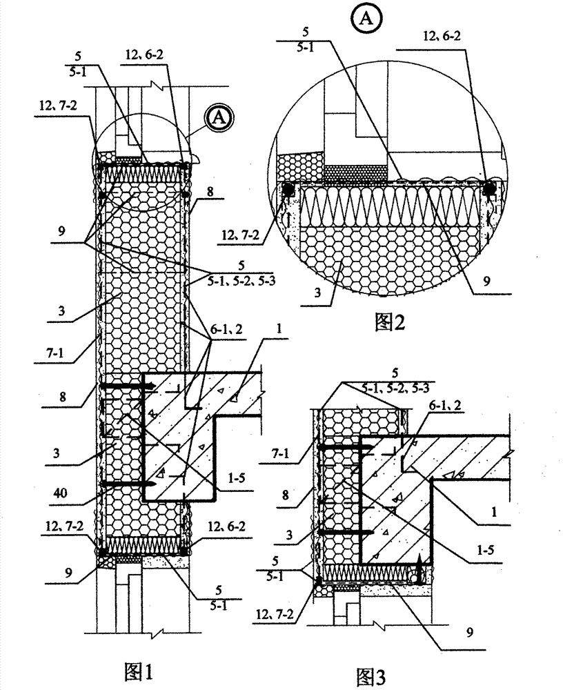
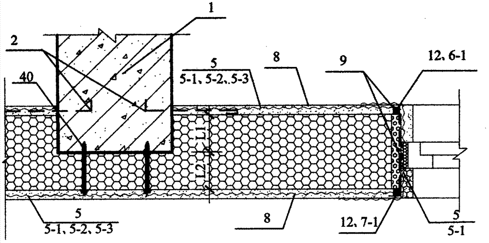
[0072] Embodiment one: see Figure 1 ~ Figure 3 , Figure 6 , Figure 10 , Figure 11 , a building thermal insulation composite wall in this embodiment is composed of a main building structure 1, cantilevered steel trusses 1-5, a core layer 3, a mesh tensile material 5, and a protective layer 8; the main building structure 1 is concrete frame structure, steel structure, wood structure and masonry columns; the core layer 3 is polymer thermal insulation material, plant straw, paper honeycomb board, thermal insulation mortar board, and the inside and outside of the core layer 3 can be Two kinds of materials, the core layer 3 in the different positions can also be different materials; the mesh tensile material 5 is a metal mesh 5-2 or an alkali-resistant mesh cloth 5-1 or a bamboo reinforcement mesh 5-3; The protective layer 8 is a plastering layer of cement mortar or fine stone concrete, or a modified cement mortar or a modified fine stone concrete plastering layer; truss, or ...

Embodiment 2

[0076] Embodiment two: see Figure 1 ~ Figure 3 , Figure 6 , Figure 12 , Figure 13 The difference between this embodiment and Embodiment 1 is that the present embodiment increases door and window reinforcing steel bars 12; section settings, see Figure 12 , or door and window reinforcing bars 12 are set along the periphery of the door and window, see Figure 13 ; The mesh tensile material 5 connects the reinforcement bars 12 of the indoor and outdoor doors and windows to each other.

[0077] The weakest part of the body of wall is exactly the hole corner position, arranging door and window reinforced steel bars 12 helps to avoid hole cracking. The Φ4 galvanized steel bar can be used as the reinforced steel bar for doors and windows, which is easy to install and has good durability. Figure 13 It is most convenient to install along the perimeter of the door and window.

[0078] Embodiments 1 and 2 use cantilevered steel trusses to hang the outdoor net-like tensile mat...

Embodiment 3

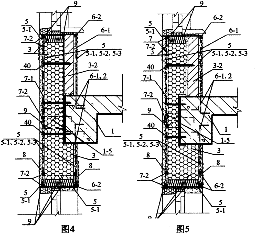
[0084] Embodiment three: see Figure 1 to Figure 6 , Figure 10 , Figure 11 , Figure 14 , Figure 16 , the difference between this embodiment and Embodiment 1 is: this embodiment adds outdoor steel bars 7, indoor steel bars 6, and internal and external pull wires 9; the core layer 3 can also be mineral wool, lightweight masonry, or the core There is also a masonry wall 3-2 on the indoor side of the layer 3, and the core layer 3 is connected with the masonry wall 3-2 to become a core layer 3 compounded with the masonry wall 3-2; the outdoor reinforcement 7 includes an outdoor Vertical steel bars 7-1, outdoor horizontal steel bars 7-2; the indoor steel bars 6 include indoor vertical steel bars 6-1, indoor horizontal steel bars 6-2; the outdoor vertical steel bars 7-1 and the cantilevered steel truss 1- 5 connection, or the outdoor vertical reinforcement 7-1 is connected to the main structure of the building 1, see Figure 16 ; The outdoor horizontal steel bar 7-2 has one o...


PUM

PropertyMeasurementUnit
thicknessaaaaaaaaaa
widthaaaaaaaaaa
thicknessaaaaaaaaaa

Abstract

The invention discloses an insulating composite wall body of a building and relates to a wall body of the building. The invention aims at solving the problems that the concrete bearing cantilever beam damages a concrete mold plate and the construction is inconvenient. The insulating composite wall body structurally comprises a building main body structure, a cantilever steel truss, a core layer and protecting layers, wherein the building main body structure is of a frame structure or a frame shear structure; the protecting layer is made of cement mortar; the core layer is made of macromolecular insulating materials, plant straws and paper honeycomb boards; the cantilever steel truss consists of steel rods and is provided with inclined rods in an erecting manner; the inner end of the cantilever steel truss is anchored with the building main body structure; the core layer is fixed inside and outside an inner frame of the building main body structure; the inner surface and the outer surface of the core layer are provided with the protecting layers; the core layer is connected with the protecting layers; net-shaped tensile materials are positioned in the protecting layers or alkali-resistant net cloth is bonded on the surfaces of the protecting layers; net-shaped tensile materials, steel bars and the cantilever steel truss are connected; therefore, the insulating composite wall body provided with the cantilever steel truss is formed. The insulating composite wall body disclosed by the invention has the advantages that the structure is simple, the safety is good, the construction is convenient, and the cost is low. The insulating composite wall body is a light energy-saving wall body and can meet the requirements such as curtain-wall decoration.

Description

technical field [0001] The invention relates to a building thermal insulation composite wall. Background technique [0002] 1. Some energy-saving wall technologies use connectors to fix the metal mesh in the plastering protection layer outside the insulation layer. These connectors have poor rigidity, are not fireproof, or have too many thermal bridges, such as: [0003] The protective layer of rubber powder polystyrene particle energy-saving and thermal insulation wall technology is equipped with a metal mesh. When connecting with the hollow block wall, the metal mesh and the base wall are fixed with Tox expansion nails. [0004] In the local standard DB23 / 1167 of Heilongjiang Province, the plastic connecting bridge (this plastic connecting bridge is a plastic sheet with a thickness of about 3mm and a width of about 30mm, with bayonet joints at both ends) connects the benzene plate module with dovetail groove and the cast-in-place concrete Fixing, this plastic connecting b...

Claims


Application Information

Patent Timeline
Patent Type & Authority Applications(China)
IPC IPC(8): E04B2/00E04B2/56E04B1/76
CPCY02A30/00Y02A30/244Y02B30/90
Inventor 吴淑环
Owner 吴淑环
Why Eureka
Try Eureka