

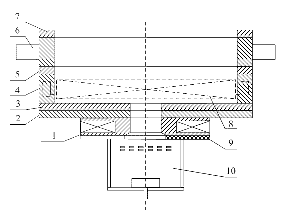
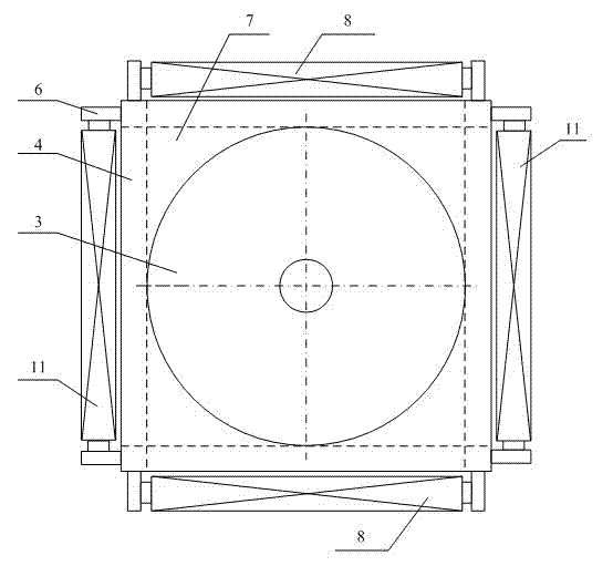
Ion source with ultra-large ion beam divergence angle
An ion beam and ion source technology, applied in the field of ion sources, can solve the problems of difficulty in adjusting the divergence angle, the divergence angle of the ion beam cannot exceed 90°, and the uniformity of the beam current density is not good, and achieves stable output, simple structure and low cost. low effect
- Summary
- Abstract
- Description
- Claims
- Application Information
AI Technical Summary
Problems solved by technology
Method used
Image

Examples
Embodiment 1
[0058] In the preparation of optical thin films, it is usually necessary to use ion beam assisted deposition to improve the film quality of the thin film. In the process of industrialized production, especially on large and medium-sized optical coating machines, in order to make all parts assisted by ion beams during the film formation process, so that the performance of the prepared film is stable and uniform, the divergence angle of the ion beam output by the ion source needs to be very large. Large, and the beam density in each divergence direction is uniform. With the novel ion beam emission source of the present invention, when ion beam bombardment is required, the working gas is first charged, and the discharge voltage of the ion source is set to 1000eV. After the gas is discharged normally, the scanning waveform in the X and Y directions is set. Adjust the scanning frequency to 30Hz to obtain a divergent ion beam. Further increase the output peak value of the sine wave...
Embodiment 2
[0060] Installed in different coating machines, or due to the different sizes of parts, sometimes the 180° ion beam divergence angle is not required. If the divergence angle is too large, part of the ion beam will bombard the inner wall of the vacuum chamber, which will affect the quality of the film formation. At this time, it is necessary to adjust the divergence angle of the ion beam.
[0061] By adopting the novel ion beam emission source of the present invention, the peak value of the driving voltage of the electromagnetic coil in the X and Y directions is reduced, and the divergence angle of the ion beam is reduced accordingly, and the optimum divergence angle of the ion beam is adjusted to obtain the size. Since the present invention adopts the ion beam scanning mode to realize the ultra-large divergence angle of the ion beam, the residence time of the ion beam at each point in the space is completely consistent, and the ion beam current density obtained in all direction...
PUM
 Abstract
Description
Claims
Application Information